background image

7

Application Examples

Applications for the 8995 and 8997 line cards include subtending T1/E1 ATM or IMA 
devices, deploying ATM over T1 or E1, deploying ATM over T1 through Digital Loop 
Carriers (DLCs), and transmitting voice over broadband.

Subtending ATM or IMA Devices

Figure 1

 shows a scenario where excess capacity of a high speed WAN connection is 

put to use by subtending DSLAMs in neighboring buildings.

Figure 1.

Subtending Application

Deploying ATM Over T1 or E1

In 

Figure 2

, broadband services are deployed over T1 or E1, such as to customers for 

whom the bandwidth of bonded xDSL is insufficient.

Figure 2.

ATM Over T1 or E1

ALARMS

Major Minor

Fan

B

A

POWER

SERIAL

SMCM

CLOCK

A

ALARM

2

4

6

8

10

12

14

16

18

1

3

5

7

9

11

13

15

17

LAN/WAN  SLOT

B

CLOCK

B

A

SERIAL

MCC

AC

ALARM

48V R

T

N

48V NEG

POWER ENTRY MODULE

LEFT UNIT: LINE A

RIGHT UNIT: LINE B

WARNING!

 POWER MUST BE DISCONNECTED AT THE SOURCE

BEFORE REMOVING OR INSTALLING THIS PWR ENTRY MODULE

48V R

TN

48V NEG

POWER ENTRY MODULE

LEFT UNIT: LINE A

RIGHT UNIT: LINE B

WARNING!

 POWER MUST BE DISCONNECTED AT THE SOURCE

BEFORE REMOVING OR INSTALLING THIS PWR ENTRY MODULE

M

C

P

80

00

SY

STE

M OK Alrm

Tes

t

TX RX Coll

ET

HE

RN

ET

SYS

TEM OK

Alrm Test

TX RX Col

1

2

3

4

ETH

ER

NET

DS

L POR

T

R

A

D

S

L

85

46

TM

TM

STACK

POSITION

2

3

6

5

4

1

AC

INPUT

1

2

3

ESD

ESD

48VDC CLA

SS 2

OR LIMITE

D

PWR SOU

RCE

A

B

DC FUSES

T4A, MIN. 4

8V

PWR

A

ALM

FAN

B

OUT

IN

SERIAL

ALM INTF

MCP/1

2

3

MCP/

DSL

8610

48V

A

RTN

A B

B

DSL PORTS 1

-24

POTS 1-24

1
2

23
24

3
4

5
6

7
8

9
10

11
12

13
14

15
16

17
18

19
20

21
22

GranDSLAM 4200

with T1 or E1

8-Port T1/E1

IMA SCM Card

T1/E1 IMA Line Card

ATM

DS-3

OC-3

IMA

04-17494

ALARMS

Major Minor

Fan

B

A

POWER

SERIAL

SMCM

CLOCK

A

ALARM

2

4

6

8

10

12

14

16

18

1

3

5

7

9

11

13

15

17

LAN/WAN  SLOT

B

CLOCK

B

A

SERIAL

MCC

AC

ALARM

48V R

T

N

48V NEG

POWER ENTRY MODULE

LEFT UNIT: LINE A

RIGHT UNIT: LINE B

WARNING!

 POWER MUST BE DISCONNECTED AT THE SOURCE

BEFORE REMOVING OR INSTALLING THIS PWR ENTRY MODULE

48V R

T

N

48V NEG

POWER ENTRY MODULE

LEFT UNIT: LINE A

RIGHT UNIT: LINE B

WARNING!

 POWER MUST BE DISCONNECTED AT THE SOURCE

BEFORE REMOVING OR INSTALLING THIS PWR ENTRY MODULE

ATM T1/E1

or

ATM T1/E1

IMA Device

ATM

DS-3

OC-3

IMA

04-17495

Summary of Contents for 8995

Page 1: ...nt 2 Product Documentation Online 4 T1 and E1 Line Cards Description 5 Application Examples 7 Installation Overview 10 Installing T1 and E1 Line Cards 10 Front Panel LEDs 12 Cabling 13 Logging In to t...

Page 2: ...Licensee acquires no title right or interest in the Software other than the license granted under this Agreement 2 Licensee shall not use the Software in any country other than the country in which th...

Page 3: ...on to another 6 IN NO EVENT WILL PARADYNE BE LIABLE TO LICENSEE FOR ANY CONSEQUENTIAL INCIDENTAL PUNITIVE OR SPECIAL DAMAGES INCLUDING ANY LOST PROFITS OR LOST SAVINGS LOSS OF BUSINESS INFORMATION OR...

Page 4: ...e call 1 727 530 2000 Document Number Document Title 8400 A2 GB20 Shelf Concentration and Processing SCP Card with ATM Uplink User s Guide 8400 A2 GB21 Shelf Concentration and Processing SCP Card with...

Page 5: ...statistics Each 8995 T1 line card supports ESF framing B8ZS line code Each 8997 E1 line card supports G 703 framing HDB3 line code 75 Ohm or 120 Ohm operation ATM Features ATM features include suppor...

Page 6: ...e support for ATM Forum Inverse Multiplexing Specification Version 1 1 1 8 IMA groups IMA configuration by port Automatic compensation for link differential delays up to 100 ms Selectable IMA frame le...

Page 7: ...NIT LINE A RIGHT UNIT LINE B WARNING POWER MUST BE DISCONNECTED ATTHE SOURCE BEFORE REMOVING OR INSTALLINGTHIS PWR ENTRY MODULE MCP 8000 SYST EM OK Alrm Test TX RX Coll ETH ERN ET SYS TEM OK Alrm Test...

Page 8: ...TN 48V NEG POWER ENTRY MODULE LEFT UNIT LINE A RIGHT UNIT LINE B WARNING POWER MUST BE DISCONNECTED ATTHE SOURCE BEFORE REMOVING OR INSTALLINGTHIS PWR ENTRY MODULE ATM T1 E1 or ATM T1 E1 IMA Device AT...

Page 9: ...15 17 LAN WAN SLOT B CLOCK B A SERIAL MCC AC ALARM 48V RTN 48V NEG POWER ENTRY MODULE LEFT UNIT LINE A RIGHT UNIT LINE B WARNING POWER MUST BE DISCONNECTED ATTHE SOURCE BEFORE REMOVING OR INSTALLINGTH...

Page 10: ...RECAUTIONS FOR STATIC SENSITIVE DEVICES This product is designed to protect sensitive components from damage due to electrostatic discharge ESD during normal operation When performing installation pro...

Page 11: ...ully the SYSTEM OK LED begins to pulse If the LED is not pulsing notify your service representative See Front Panel LEDs on page 12 5 Secure the unit by fastening the screws at each end of the facepla...

Page 12: ...ped No power to card Card is functioning normally Alrm Amber On Off Alarm is present on the card Normal operation no alarms Test Amber On Off Test in progress Normal operation no tests ATM BUS TX Off...

Page 13: ...cedure To fasten the Telco connector to the chassis using the provided cable ties 1 Replace the longer captive screw on the cable connector with the 4 40 Phillips pan head screw shipped in a plastic b...

Page 14: ...crew on the cable connector with the 4 40 Phillips pan head screw shipped in a plastic bag with the BLC 2 Install the locking pivot bracket onto the cable end of the connector using the captive screw...

Page 15: ...ully seated 7 Tighten the captive screw on the top of the cable s connector 8 If a ferrite choke is included with your T1 or E1 card install it on the cable as close as possible to the chassis If the...

Page 16: ...on screens listed depend on the types of line cards and SCP card installed in the chassis Configuration The following list shows the web interface Configuration screens most likely to require modifica...

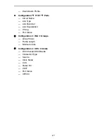
Page 17: ...Name Line Type Line Build Out Line Equalization Timing Port Status Configuration IMA Groups Group Status Frame Length Minimum Links Configuration CES Create DS0 Channel DS0 Bundle Connection Type Serv...

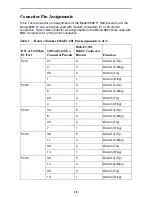
Page 18: ...mber 8026 F1 001 Pin Assignments 1 of 2 DS1 or 120 Ohm E1 Port 50 Position Telco Connector Pinouts 8026 F1 001 RJ48C Connector Pinouts Function Port 1 27 5 Data Out Tip 2 4 Data Out Ring 26 2 Data In...

Page 19: ...Table 2 Feature Number 8027 F1 001 Pin Assignments 1 of 2 75 Ohm E1 Port Function 50 Position Telco Connector Pinouts BNC Connector Port 1 Data In 1 Shell Ring 26 Pin Tip Data Out 2 Shell Ring 27 Pin...

Page 20: ...Data Out 14 Shell Ring 39 Pin Tip Port 6 Data In 16 Shell Ring 41 Pin Tip Data Out 17 Shell Ring 42 Pin Tip Port 7 Data In 19 Shell Ring 44 Pin Tip Data Out 20 Shell Ring 45 Pin Tip Port 8 Data In 22...

Page 21: ...ing temperature Storage temperature Relative humidity Shock and vibration 40 to 149 F 40 to 65 C 4 F to 158 F 20 C to 70 C 5 to 85 noncondensing Withstands normal shipping and handling T1 and E1 Speci...

Page 22: ...ak with a company representative Within the U S A call 1 800 870 2221 Outside the U S A call 1 727 530 2340 Document Feedback We welcome your comments and suggestions about this document Please mail t...

Page 23: ...23...

Page 24: ...24 8990 A2 GN10 20 8990 A2 GN10 20...

Reviews: