background image

6382-A2-GB20-00

April 2005

B

 Important Safety Instructions

1. Read and follow all warning notices and instructions marked on the product or included in the manual.

2. Slots and openings in the cabinet are provided for ventilation. To ensure reliable operation of the product and to 

protect it from overheating, these slots and openings must not be blocked or covered.

3. Do not allow anything to rest on the power cord and do not locate the product where persons will walk on the power 

cord.

4. Do not attempt to service this product yourself, as opening or removing covers may expose you to dangerous high 

voltage points or other risks. Refer all servicing to qualified service personnel.

5. General purpose cables are used with this product for connection to the network. Special cables, which may be 

required by the regulatory inspection authority for the installation site, are the responsibility of the customer. Use a 
UL Listed, CSA certified, minimum No. 24 AWG line cord for connection to the Digital Subscriber Line (DSL) 
network.

6. When installed in the final configuration, the product must comply with the applicable Safety Standards and 

regulatory requirements of the country in which it is installed. If necessary, consult with the appropriate regulatory 
agencies and inspection authorities to ensure compliance.

7. A rare phenomenon can create a voltage potential between the earth grounds of two or more buildings. If products 

installed in separate buildings are interconnected, the voltage potential may cause a hazardous condition. Consult 
a qualified electrical consultant to determine whether or not this phenomenon exists and, if necessary, implement 
corrective action prior to interconnecting the products.

8. Input power to this product must be provided by one of the following: (1) a UL Listed/CSA certified power source 

with a Class 2 or Limited Power Source (LPS) output for use in North America, or (2) a certified transformer, with a 
Safety Extra Low Voltage (SELV) output having a maximum of 240 VA available, for use in the country of 
installation.

9. In addition, since the equipment is to be used with telecommunications circuits, take the following precautions:

Never install telephone wiring during a lightning storm.

Never install telephone jacks in wet locations unless the jack is specifically designed for wet locations.

Never touch uninsulated telephone wires or terminals unless the telephone line has been disconnected at the 
network interface.

Use caution when installing or modifying telephone lines.

Avoid using a telephone (other than a cordless type) during an electrical storm. There may be a remote risk of 
electric shock from lightning.

Do not use the telephone to report a gas leak in the vicinity of the leak.

CE Marking

When the product is marked with the CE mark on the equipment label, a supporting Declaration of Conformity may be 
downloaded from the Paradyne World Wide Web site at 

www.paradyne.com

. Select 

Library 

 Technical Manuals 


CE Declarations of Conformity

.

FCC Part 15 Declaration

An FCC Declaration of Conformity may be downloaded from the Paradyne World Wide Web site at www.paradyne.com. 
Select Support -> Technical Manuals -> Declarations of Conformity.

This device complies with Part 15 of the FCC Rules. Operation is subject to the following two conditions: (1) this device 
may not cause harmful interference, and (2) this device must accept any interference received, including interference 
that may cause undesired operation.

The authority to operate this equipment is conditioned by the requirement that no modifications will be made to the 
equipment unless the changes or modifications are expressly approved by the responsible party. 

!

Summary of Contents for 6382

Page 1: ...6382 4 Port Router User s Guide Document No 6382 A2 GB20 00 April 2005 ...

Page 2: ...cumentation training distributor locations or Paradyne worldwide office locations use one of the following methods Internet Visit the Paradyne World Wide Web site at www paradyne com Be sure to register your warranty at www paradyne com warranty Telephone Call our automated system to receive current information by fax or to speak with a company representative Within the U S A call 1 800 870 2221 O...

Page 3: ...this product must be provided by one of the following 1 a UL Listed CSA certified power source with a Class 2 or Limited Power Source LPS output for use in North America or 2 a certified transformer with a Safety Extra Low Voltage SELV output having a maximum of 240 VA available for use in the country of installation 9 In addition since the equipment is to be used with telecommunications circuits ...

Page 4: ... with this product It has been designed to be connected to a compatible modular jack that is also compliant The Ringer Equivalence Number or REN is used to determine the number of devices that may be connected to a telephone line Excessive RENs on a telephone line may result in the devices not ringing in response to an incoming call In most but not all areas the sum of RENs should not exceed five ...

Page 5: ...al Officer Notice to Users of the Canadian Telephone Network NOTICE This equipment meets the applicable Industry Canada Terminal Equipment Technical Specifications This is confirmed by the registration number The abbreviation IC before the registration number signifies that registration was performed based on a Declaration of Conformity indicating that Industry Canada technical specifications were...

Page 6: ...he standard of the Voluntary Control Council for Interference from Information Technology Equipment VCCI If this is used near a radio or television receiver in a domestic environment it may cause radio interference Install and use the equipment according to the instruction manual ...

Page 7: ... Panel 1 3 Packing List 1 3 2 Hardware Installation and PC Setup Overview 2 1 Connecting the Hardware 2 1 Configuring Your PC s IP Address 2 3 Assigning an IP Address to your PC Automatically by DHCP 2 3 Windows XP 2 3 Windows 2000 2 5 Windows ME 2 6 Windows 95 98 2 7 Windows NT 4 0 2 8 3 Using the Web Interface Logging Into Your Router 3 1 Home Page 3 2 Quick Start 3 2 Setup 3 5 Wide Area Network...

Page 8: ... Disable DHCP 3 18 Changing the Router s IP address 3 19 Ethernet Switch 3 20 Firewall NAT Services 3 21 Advanced 3 22 UPnP 3 22 SNTP 3 23 SNMP 3 24 IP QoS 3 25 Port Forwarding 3 25 IP Filters 3 27 LAN Clients 3 28 VLAN 3 28 Bridge Filters 3 29 Multicast 3 31 IGMP Snooping 3 32 Static Routing 3 32 Dynamic Routing 3 33 Access Control 3 35 Log Out 3 35 Tools 3 36 System Commands 3 36 Remote Log 3 36...

Page 9: ...outer Is Not Functional 4 1 You Cannot Connect to the Router 4 2 LEDs Blink in a Sequential Pattern 4 2 Status LED Continues to Blink 4 2 Status LED is Always Off 4 2 A Terminology What is a Firewall A 1 What is NAT A 1 What is a DMZ A 1 What is a Router A 2 Index ...

Page 10: ...Contents iv April 2005 6382 A2 GB20 00 ...

Page 11: ... paradyne com Select Support Technical Manuals To order a paper copy of a Paradyne document or to speak with a sales representative please call 1 727 530 2000 Section Description Chapter 1 Introduction Describes the features of the router Chapter 2 Hardware Installation and PC Setup Shows how to connect the router and set up your PC to manage the router Chapter 3 Using the Web Interface Explains h...

Page 12: ...About This Guide vi April 2005 6382 A2 GB20 00 ...

Page 13: ...nes too long or too noisy for ADSL ADSL R is technology that combines ADSL and ReachDSL in one device The Model 6382 is a Digital Subscriber Line DSL modem that may be set by you to run in bridge or router mode Because it is most frequently used as a router that is how it is referred to in this manual It supports ADSL R Features of the 6382 4 Port Router Your router has the following features 4 Po...

Page 14: ...later Ports and Buttons Back Panel LINE port This is the DSL interface which connects directly to your phone line PHONE port This allows a phone to directly connect to the router You do not need to add splitter to the phone you connect here since the router has an internal splitter RESET Button The RESET button is used to reset the router to the default settings selected by your service provider D...

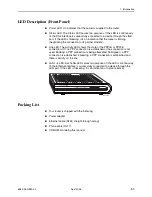
Page 15: ...PPoE connection Off no PPP connection is established or the connection is not used Blinking a PPP connection is being attempted Solid green a PPP connection is established Flickering a PPP connection is established and there is activity on the link LAN 1 4 LED Each LAN LED serves two purposes If the LED is continuously lit the Ethernet interface is successfully connected to a device through the LA...

Page 16: ...1 Introduction 1 4 April 2005 6382 A2 GB20 00 ...

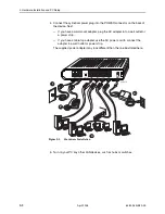
Page 17: ...nnect your router Procedure 1 Connect the supplied modular phone cable to the LINE port and connect the other end of the cable to your phone jack 2 If you would like to use a phone in the vicinity of the router connect it to the PHONE jack of the router using the cord that came with your telephone The router has an internal POTS filter so you do not need to install one here 3 Use the included Ethe...

Page 18: ...e AC adapter into a wall outlet or a power strip If you have a table top adapter use the AC power cord to connect the adapter to a wall outlet or power strip The supplied power adapter may look different than the one illustrated here Figure 2 1 Hardware Installation 5 Turn on your PC any other LAN devices such as hubs or switches 04 17576 1 2 3 4 LINE LAN 4 POWER PHONE DEFAULT RESET LAN 3 LAN 2 LA...

Page 19: ...an IP address automatically instead of Use the following IP address in the following procedures By default the LAN port IP address of the router is 192 168 1 1 You can change this address or another address can be assigned by your ISP Windows XP To configure the IP address under Windows XP Procedure 1 In the Windows task bar click on the Start button and then click on Control Panel 2 Double click ...

Page 20: ...il 2005 6382 A2 GB20 00 4 Ensure that the check box to the left of the item labeled Internet Protocol TCP IP is checked and click on Properties Figure 2 2 Network Connections in Windows XP Figure 2 3 Local Area Connection Properties in Windows XP ...

Page 21: ...lose the Control Panel Windows 2000 To configure the IP address under Windows 2000 Procedure 1 In the Windows task bar click on the Start button point to Settings and then select Control Panel 2 Double click on the Network and Dial up Connections icon 3 In the Network and Dial up Connections window right click on the Local Area Connection icon and then select Properties The Local Area Connection P...

Page 22: ...et Protocol TCP IP Properties dialog box click in the radio button labeled Use the following IP address and type 192 168 1 x where x is any number between 2 and 254 in the IP Address field Type 255 255 255 0 in the Subnet Mask field 12 Click on OK twice to confirm and save your changes and then close the Control Panel Windows ME To configure the IP address under Windows ME Procedure 1 In the Windo...

Page 23: ...hanges and then close the Control Panel Windows 95 98 To configure the IP address under Windows 95 or Windows 98 Procedure 1 In the Windows task bar click on the Start button point to Settings and then click on Control Panel 2 Double click on the Network icon The Network dialog box is displayed with a list of currently installed network components If the list includes TCP IP the protocol has alrea...

Page 24: ...talled network protocols If the list includes TCP IP the protocol has already been enabled in which case you can skip to Step 9 4 If TCP IP does not appear as an installed component click on Add 5 In the Select Network Protocol dialog box select TCP IP and then click on OK You may be prompted to install files from your Windows NT installation CD or other media Follow the instructions to install th...

Page 25: ...r name is Admin and the password is Admin Both are case sensitive Note Before configuring your router make sure you have followed the instructions in Chapter 2 Hardware Installation and PC Setup You should have your PCs configured for DHCP mode if your router will be and have proxies disabled on your browser If you see a login redirection screen when you access the web interface verify that JavaSc...

Page 26: ...er status connection information and other useful information The center display is where most of the configuration will take place Click on Log Out to close the session Refresh to update the status display or Quick Start to configure basic options Quick Start The Quick Start screen gives you immediate access to the options you are most likely to need to specify or change Click on the Quick Start ...

Page 27: ...3 Using the Web Interface 6382 A2 GB20 00 April 2005 3 3 Figure 3 3 Quick Start DHCP Figure 3 4 Quick Start PPPoE ...

Page 28: ...nology for a description of a firewall Username PPPoE Enter the user name given to you by your service provider Password PPPoE Enter the password given to you by your service provider IP Address Static Enter the IP address to be assigned to the router Mask Static Enter the subnet mask to be applied to the IP address Default Gateway Static Enter the IP address of a default gateway Packets for which...

Page 29: ... your Internet Service Provider ISP Most of the configuration you will perform will be in this area Local Area Network Connection On the other side of your router are your own Local Area Network LAN connections This is where you plug in your local computers to the router The router is normally configured to automatically provide all the PCs on your network with Internet addresses If you connected ...

Page 30: ...ltiplexing mode Your DSL training mode default is MMODE If you use PPPoA or PPPoE you also need these values from your ISP Your username and password If you use multiprotocol encapsulation over ATM Adaptation Layer 5 as described in RFC 1483 you may need these values from your ISP Your DSL fixed Internet IP address Your subnet mask Your default gateway IP address Your primary DNS IP address Since ...

Page 31: ...d 3 Give your PPPoE connection a unique name The name must not have spaces and cannot begin with numbers 4 Select a PVC Sharing type of Disable Enable or VLAN 5 Select or enter a VPI and VCI as supplied by your DSL service provider or your ISP or click in Auto PVC Auto PVC causes the router to perform automatic VPI VCI detection as defined in DSL forum TR 068 For VLAN specify a VLAN ID and priorit...

Page 32: ...e Maximum Transmission Unit the DSL connection can send It is a negotiated value The maximum specified value is 1500 although some DSL ISP providers require a larger value The minimum MTU value is 128 On Demand Enables on demand mode The connection will disconnect if no activity is detected after the specified idle timeout value Default Gateway Specifies whether a default gateway is used Enforce M...

Page 33: ...The default PPPoE connection setup is displayed 2 At the Type field select PPPoA from the drop down list The PPPoA connection setup page is displayed 3 Give your PPPoA connection a unique name The name must not have spaces and cannot begin with numbers 4 Select or enter a VPI and VCI as supplied by your DSL service provider or your ISP or click in Auto PVC Auto PVC causes the router to perform aut...

Page 34: ...the On Demand option is not enabled this value specifies the length of time to keep the connection from being shut down for inactivity by sending PPP LCP echoes to the PPP server To ensure that the link is always active enter a zero in this field MTU The Maximum Transmission Unit the DSL connection can send It is a negotiated value The maximum specified value is 1500 although some DSL ISP provider...

Page 35: ...ust not have spaces and cannot begin with numbers 4 Optionally enable Network Address Translation NAT and the Firewall options Firewall and NAT services must be enabled See Firewall NAT Services on page 3 21 5 Select a PVC Sharing type of Disable Enable or VLAN 6 Select or enter a VPI and VCI as supplied by your DSL service provider or your ISP or click in Auto PVC Auto PVC causes the router to pe...

Page 36: ...o assignment To configure the router for a DHCP connection Procedure 1 Click on Setup and then click on New Connection The default PPPoE connection setup is displayed 2 At the Type field select DHCP The DHCP connection setup page is displayed 3 Give your DHCP connection a unique name The name must not have spaces and cannot begin with numbers 4 Select a PVC Sharing type of Disable Enable or VLAN 5...

Page 37: ...DVT Cell Delay Variation Tolerance If your DSL line is connected and your DSL provider is supporting DHCP you can click on the Renew button and the CPE will retrieve an IP Address Subnet Mask and Default Gateway address At any time you can renew the DHCP address by clicking on the Renew button Figure 3 10 DHCP Connection Setup To complete the connection you must now click the Apply button The Appl...

Page 38: ... see Figure 3 11 3 Give your Bridge connection a unique name the name must not have spaces and cannot begin with numbers 4 Select a PVC Sharing type of Disable Enable or VLAN 5 Select or enter a VPI and VCI Your DSL service provider or your ISP will supply these For VLAN specify a VLAN ID and priority 6 Select the encapsulation type LLC or VC if you are not sure which to use just use the default m...

Page 39: ...lt PPPoE connection setup is displayed 2 At the Type field select CLIP and the CLIP connection setup page is displayed 3 Give your CLIP connection a unique name the name must not have spaces and cannot begin with numbers 4 Select or enter a VPI and VCI as supplied by your DSL service provider or your ISP or click in Auto PVC Auto PVC causes the router to perform automatic VPI VCI detection as defi...

Page 40: ... at the top of the page and select System Commands At the System Commands page click on Save All Modify an Existing Connection To modify an existing connection Procedure 1 From the Home screen click on Setup 2 Click on the connection you want to modify The connections are listed by name If you delete a connection to make the change permanent click on Tools at the top of the page and select System ...

Page 41: ...odem This will bring up the Modem Setup screen Leave the default value if your ISP did not provide this information For most cases this screen should not be modified Figure 3 13 Modem Setup The Apply button will temporarily save these settings To make the change permanent click on Tools at the top of the page and select System Commands At the System Commands page click on Save All ...

Page 42: ...nning on your network do not enable a second DHCP server To enable DHCP Procedure 1 From the Home screen click on Setup 2 Under LAN Setup select LAN Configuration The LAN Group 1 Configuration screen appears Figure 3 14 LAN Group 1 Configuration 3 The DHCP server is enabled when Enable DHCP Server is selected If you enable it Specify a Start IP address The Start IP Address is where the DHCP server...

Page 43: ...DHCP relay it is responsible for forwarding the requests and responses negotiating between the DHCP clients and the server If the DHCP server and relay are turned off you must configure the IP address subnet mask and DNS settings of every computer on your network Do not assign the same IP address to more than one computer Your router must be on the same subnet as the computers The Apply button wil...

Page 44: ...ve All Ethernet Switch To set the speed and duplex mode of the LAN ports Procedure 1 From the Home screen click on Ethernet Switch The Ethernet Switch screen appears 2 For Physical Port1 through Physical Port4 LAN1 through LAN4 select a mode and speed from the Set Value drop down list Select Auto to negotiate the Ethernet duplex mode and speed with attached equipment that supports auto negotiation...

Page 45: ...nselecting the Enable Firewall and NAT Services button the firewall and NAT services is disabled for all WAN connections Enabling Firewall NAT does not automatically apply it to connections The Apply button will temporarily save this setting To make the change permanent click on Tools at the top of the page and select System Commands At the System Commands page click on Save All Figure 3 16 Firewa...

Page 46: ...active DSL connection In the presence of multiple DSL connections select the one over which the incoming traffic will be present such as the default Internet connection To enable UPnP you must first have a WAN connection configured Once a WAN connection is configured Procedure 1 From the Home screen click on Advanced and under Advanced select UPnP The UPnP screen appears 2 Enable UPnP and then sel...

Page 47: ...o use SNTP Procedure 1 From the Home screen click on Advanced and under Advanced select SNTP The SNTP screen appears 2 Enable SNTP and then specify one or more SNTP servers 3 The Apply button will temporarily save these settings To make the change permanent click on Tools and select System Commands On the System Commands page click on Save All Figure 3 18 SNTP ...

Page 48: ...lic sysObjectID for the router IP address of the agent sending the trap Time stamp sysUpTime Serial Number of the router IP address of the router Interface name To configure SNMP Procedure 1 From the Home screen click on Advanced and under Advanced select SNMP The SNMP screen appears 2 Enable the SNMP traps then enter up to five Destination IP Addresses and Community names The Apply button will te...

Page 49: ... Using the Port Forwarding page you can provide local services such as web hosting for people on the Internet When users send this type of request to your network via the Internet the router will forward those requests to the appropriate PC Port forwarding can be used with DHCP assigned addresses but remember that a DHCP address is dynamic If you were configuring a Netmeeting server for example yo...

Page 50: ...screen click on Advanced and under Advanced select Port Forwarding First select the IP address for your Netmeeting server Next select the Audio Video category and add Netmeeting to the Applied Rules box To view the management rules highlight Netmeeting and select view This will display the preconfigured protocols and ports that Netmeeting will use Now you can run Netmeeting from your server and ca...

Page 51: ...he LAN Group from the drop down list that these changes will apply to 3 Select a LAN IP address from the LAN IP drop down list Click on New IP to add a new IP address to the list 4 Select available rules from the list or click on Custom IP Filters to create a new rule 5 Click on Apply The Apply button will temporarily save these settings To make the change permanent click on Tools and select Syste...

Page 52: ... address Once the IP address has been added to you can apply Port Forwarding rules to this IP address 3 The Apply button will temporarily save these settings To make the change permanent click on Tools and select System Commands On the System Commands page click on Save All Figure 3 23 LAN Clients VLAN You can use the VLAN Virtual Local Area Network screen to match different VLAN IDs to the LAN po...

Page 53: ...me screen click on Advanced 2 Under Advanced select Bridge Filters The Bridge Filters screen appears as shown in Figure 3 25 Bridge Filters The User Interface for Bridge Filter allows the user to add edit and delete as well as enable the filter rules To add rules define the source MAC address destination MAC address and frame type with the desired filtering action allow or deny and click on the Ad...

Page 54: ...ese rules are entered automatically by the system to ensure that you don t lock yourself out of the system The first rule allows all ARP frames through the system The second rule allows all IPv4 frames with the destination MAC address of the router to go through The third rule allows all IPv4 frames with the source MAC address of the router to go through The Apply button will temporarily save thes...

Page 55: ...t groups It should only be enabled if NAT is also enabled To enable Multicasting Procedure 1 From the Home screen click on Advanced 2 Under Advanced select Muliticast 3 The Apply button will temporarily save these settings To make the change permanent click on Tools and select System Commands On the System Commands page click on Save All Figure 3 26 Multicast ...

Page 56: ... Apply button will temporarily save these settings To make the change permanent click on Tools and select System Commands On the System Commands page click on Save All Figure 3 27 IGMP Snooping Static Routing If the router is connected to more than one network you may need to set up a static route between the networks A static route is a predefined pathway that network information must travel to r...

Page 57: ...en the router and the remote network or host 5 Specify the Metric This determines the maximum number of steps between network nodes that data packets will travel A node is any device on the network such as a router or switch 6 The Apply button will temporarily save these settings To make the change permanent click on Tools and select System Commands On the System Commands page click on Save All Fi...

Page 58: ...v2 format using multicasting 4 Specify the Direction This determines the direction that RIP routes will be updated Selecting In means that the router will only incorporate received RIP information Selecting Out means that the router will only send out RIP information Selecting both means that the router will incorporate received RIP information and send out updated RIP information 5 The Apply butt...

Page 59: ...tion To enable any of the Access Control features Procedure 1 From the Home screen click on Advanced 2 Under Advanced select Access Control The Access Control screen appears All Access Control rules have precedence over rules that were added via the Port Forwarding page 3 The Apply button will temporarily save these settings To make the change permanent click on Tools and select System Commands On...

Page 60: ... to the unit will be lost You can reconnect after the unit reboots Restore Defaults Use this button to restore the default settings selected by your service provider Connectivity to the unit will be lost You can reconnect after the unit reboots Figure 3 31 System Commands Remote Log The remote log feature forwards all logged information to a remote PC The type of information forwarded to the remot...

Page 61: ...everity Levels Severity Level Description Panic System panic or other condition that causes the router to stop functioning Alert Conditions that require immediate correction such as a corrupted system database Citical Potentially critical conditions such as hard drive errors Error Error conditions that generally have less serious consequences than errors in the panic alert and critical levels Warn...

Page 62: ...this screen The idle timeout determines after how many minutes of inactivity the web interface is logged off The Apply button will temporarily save these settings To make the change permanent click on Tools at the top of the page and select System Commands At the System Commands page click on Save All If you forget your password you can press and hold the reset to factory defaults button for 10 se...

Page 63: ...ate Gateway 2 Click on Browse and find the firmware file to download Make sure this is the correct file 3 Click on upgrade firmware Once the upgrade is complete the CPE will reboot You will need to log back onto the CPE after the firmware upgrade is complete The firmware upgrade should take less that 5 minutes to complete If it takes longer than 5 minutes something has gone wrong Caution Do not re...

Page 64: ...3 Using the Web Interface 3 40 April 2005 6382 A2 GB20 00 Figure 3 34 Update Gateway Analyzer The Analyzer screen shows link statuses and test results Figure 3 35 Analyzer ...

Page 65: ...e able to access the Internet To run a ping test Procedure 1 From the Home screen under the Tools title click on Ping Test 2 Specify the target IP Address that you want to ping Optionally specify TOS Byte value This is part of the IP header of the ping packet Valid values are 0 to 255 Packet size Valid values are 36 to 65507 Number of echo requests Valid values are 1 to 9 3 Click on Test By defaul...

Page 66: ...nd and segment tests The test may take a few seconds to complete To perform the test select your connection from the list select a Test Type and click on the Test button Before running this test make sure you have a valid DSL link if the DSL link is not connected this test will always fail Also the DSLAM must support this feature Not all DSLAMs have OAM F4 and F5 support Figure 3 37 Modem Test ...

Page 67: ...s Statistics of different connections and interfaces Network Statistics Select to view the Statistics of the Ethernet and DSL interfaces as shown in Figure 3 38 Figure 3 38 Network Statistics Connection Status Select to view the Status of different connections DHCP Clients Select to view the list of DHCP clients ...

Page 68: ... in Figure 3 39 Figure 3 39 Modem Status Product Information Select to view the router s driver and run time information as shown in Figure 3 40 Figure 3 40 Product Information System Log Select to view all logged information Depending upon the severity level this logged information will generate log reports to a remote host if remote logging is enabled ...

Page 69: ...ore details 5 Check the router s settings 6 From your PC can you ping the router Assuming that the router has DHCP enabled and your PC is on the same subnet as the router you should be able to ping the router 7 Can you ping the WAN Your ISP should have provided the IP address of their server If you can ping the router and your protocols are configured correctly you should be able to ping the ISP s...

Page 70: ...attern This typically means that either the kernel or flash file system is corrupted Notify your service representative Status LED Continues to Blink This means that the DSL line is trying to train but for some reason it cannot establish a valid connection The main cause of this is that you are too far away from the central office Contact your DSL service provider for further assistance Status LED...

Page 71: ... with However you may have several machines on your local network that want to access the Internet at the same time The router provides NAT functionality that converts your local network addresses to the single network address provided by your ISP It keeps track of all these connections and makes sure that the correct information gets to the correct local machine Occasionally there are certain pro...

Page 72: ...tation solves the problem of supporting a large number of stations but introduces the problem of getting traffic from one subnet to another To accomplish this devices called routers are placed between segments If a machine wishes to contact another device on the same segment it transmits to that station directly using a simple discovery technique If the target station does not exist on the same se...

Page 73: ...tion Setup 3 12 Enable Disable 3 18 DMZ Explained A 1 DoC D Document Feedback A Purpose and Intended Audience v Summary v duplex mode 3 20 Dynamic Routing 3 33 E EMI Notice Canada D Japan E Enable Disable DHCP 3 18 ending session 3 35 end to end test 3 42 Ethernet cable 2 1 switch configuration 3 20 F factory default settings 1 2 FCC Part 15 Declaration B Features of the Router 1 1 filters bridge ...

Page 74: ...acking List 1 3 Password 3 1 PC Setup 2 1 Ping Test 3 41 Port Forwarding 3 25 port speed 3 20 Ports and Buttons Back Panel 1 2 Power LED 1 3 power supply 2 2 PPPoA Connection Setup 3 9 PPPoE Connection Setup 3 7 Support 1 2 Product Related Documents v PVC Support 1 2 Q QoS 3 25 Quality of Service 3 25 Quick Start Options 3 4 R ReachDSL 1 1 Remote Logging 3 36 Requirements 1 2 Reset Button 1 2 Rout...

Page 75: ...aps 3 24 Troubleshooting 4 1 4 2 U Update Gateway 3 39 Upgrade Firmware 3 39 UPnP 3 22 User Management 3 38 Username 3 1 V VLAN 3 28 W WAN Configuring 3 6 Connection 3 5 Warranty Sales Service and Training Information A Web Interface using 3 1 Wide Area Network Connection 3 5 Windows 2000 2 5 95 98 2 7 ME 2 6 NT 4 0 2 8 XP 2 3 ...

Page 76: ...Index IN 4 April 2005 6382 A2 GB20 00 ...

Reviews: