1
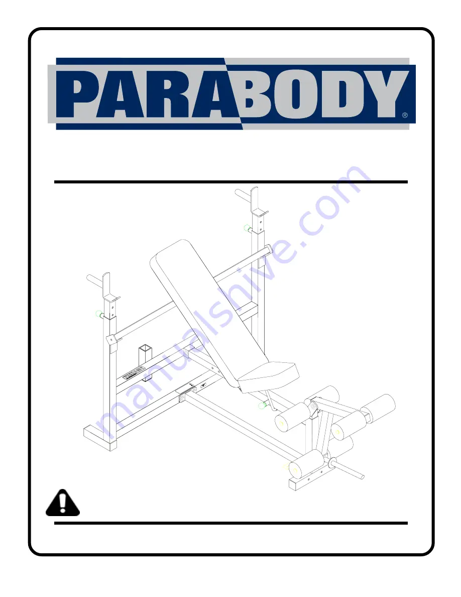
807 BODY SYSTEM
WORKOUT CENTER
CLASS HPART # 7304201REV. A
Revision: 06/19/02
USER’S GUIDE
WARNING:
Read and follow all directionsfor each step to insure properassembly of this product.
Version: 807108
Page 1: ...1 807 BODY SYSTEM WORKOUT CENTER CLASS H PART 7304201 REV A Revision 06 19 02 USER S GUIDE WARNING Read and follow all directions for each step to insure proper assembly of this product Version 807108...
Page 2: ...se the machine if found in this condition DO NOT attempt to fix Notify your authorized ParaBody dealer 7 Inspect cables and their connections before using machine Pay particular attention to the cable...
Page 3: ...oper function 3 NOTE BOLT LENGTH IS MEASURED FROM THE UNDERSIDE OFTHE HEAD OFTHE BOLT BOLT LENGTH RULER This product must be assembled on a flat level surface to assure its proper function DO NOT secu...
Page 4: ...1 Square 1 X 1 4 1 2 3 4 5 6 7 1 5 4 3 2...
Page 5: ...6 2 6 2 3 1 6 DESCRIPTION UPRIGHT FRAME BENCH FRAME HEIGHT ADJUSTMENT BAR WOLFF SLEEVE BASE LEG SADDLE LEG EXTENSION NECK LEG EXTENSION HINGE TAB U PIN ROLLER PAD SHAFT ROLLER PAD SEAT PAD BACK PAD 3...
Page 6: ...ached Remove the PARAGLIDE STRIPS from the paper backing and firmly apply them to all shown surfaces Insert one U PIN 10 through the BUSHING of the WOLFF SLEEVE 4 and attach one PAL NUT 28 to the end...
Page 7: ...nt holes Insert two 2 SQ END CAPS 33 into both ends of the BASE LEG 5 as shown in FIGURE 2 Insert one U PIN 10 through the BUSHING on the bottom of BENCH FRAME 2 and attach one PAL NUT 28 to the end o...
Page 8: ...o the UPRIGHT FRAME 1 using two 3 8 X 3 BOLTS 17 one 3 8 X 2 3 4 BOLT 16 six 3 8 WASHERS 19 and three 3 8 LOCK NUTS 21 as shown in FIGURE 3 4 2 21 19 3 8 X 3 17 19 3 8 X 2 3 4 16 21 0 1 2 3 4 5 6 1 2...
Page 9: ...in FIGURE 4 29 Slide two 1 1 4 X 5 GRIPS 30 over the DIP HANDLES of both SADDLES 6 IF A LUBRICANT IS REQUIRED COAT THE INSIDE OF THE GRIP WITH RUBBING ALCOHOL Pull back the SPRING PIN on the UPRIGHT T...
Page 10: ...he WOLFF SLEEVE 4 start by sliding two HINGE TABS 9 over the PIN of the WOLFF SLEEVE ONE ON EACH SIDE as shown in FIGURE 5 and SECURELY assemble each HINGE TAB 9 to the SEAT PAD 13 using two 3 8 X 1 B...
Page 11: ...de the two remaining HINGE TABS 9 over the PIN of the WOLFF SLEEVE ONE ON EACH SIDE as shown in FIGURE 6 and SECURELY assemble each HINGE TAB 9 to the BACK PAD 14 using two 3 8 X 1 BOLTS 15 two 3 8 LO...
Page 12: ...EXTENSION NECK 7 as shown in FIGURE 7 Slide two ROLLER PADS 12 over each end of the SHAFT of the LEG EXTENSION NECK 7 as shown in FIGURE 7 and secure in place using two 3 4 STARLOCK COLLARS 27 27 2 In...
Page 13: ...s shown in FIGURE 8 using one 1 2 X 3 BOLT 18 two 1 2 WASHERS 22 and one 1 2 LOW HEIGHT LOCK NUT 24 TIGHTEN THE CONNECTION ENOUGH TO REMOVE THE PLAY YETALLOWINGTHE LEGEXTENSION TO ROTATE FREELY Assemb...
Page 14: ...pull up slowly on the front of the BENCH FRAME 2 and allow the U PIN 10 to rest on top of the TAB of the BASE LEG 5 NOTE THE BENCH FRAME MUST BE ADJUSTED UP WHEN USINGTHE LEG EXTENSION TOALLOW PROPER...
Page 15: ...FIGURE 10 for performing INCLINE or MILITARY PRESSES When performing DIPS use the HEIGHTADJUSTMENT BAR 3 to hold the BACK PAD forward as shown in the WORKOUT MANUAL Follow the WORKOUT MANUAL for the c...
Page 16: ...purchased from your ParaBody customer service representative at 800 328 9714 Inspect equipment daily Tighten all loose connections are replace worn parts immediately Failure to do so may result in se...
Page 17: ...ve charges for returning parts to ParaBody and c all necessary or incidental costs related to installation of the replacement parts 6 SHIPPING If shipping by the Owners is deemed necessary in sole dis...
Page 18: ...64 66 99 LIFE FITNESS CONSUMER DIVISION 14150 Sunfish Lake Blvd Ramsey Minnesota 55303 U S A Tel 763 323 4500 Fax 763 323 4797 800 328 9714 Toll free within the U S and Canada www parabody com 18 Lif...