background image


BA_PH_335-20_EN_07-22.docx


19


5.3


Emission Levels 

5.3.1


Noise Information 

The values given are emission levels and therefore do not necessarily represent safe workplace values. Alt-

hough there is a correlation between emission and immission levels, it cannot be reliably deduced whether 

additional precautionary measures are necessary or not.  
Factors that may affect the current immission level at the workplace include the duration of exposure, the 

nature of the workspace, other noise sources, etc., e.g. the number of machines and other activities in the 

vicinity. The permissible workplace values can also vary from country to country. 
However, this information should enable the user to make a better assessment of hazard and risk. 

5.3.2


Noise Emission Values 

The specified measured values are determined in accordance with EN 860. 
Uncertainty allowance K = 4 dB(A) 

Workplace-related emission value


Sound power level


Idle


93 dB(A)


Idle


Lwa = 84 dB(A) 

Working


99 dB(A)


Working


Lwa = 92 dB(A) 


The workplace-related noise emission values of the machine exceed 85 dB(A)!  

Therefore, suitable hearing protection must be provided to the personnel!


Dust emission values:  

Determined according to GS-HO-05 


Workplace-related dust emission value 

(permissible 2.0 mg/m³ air)


0.48 mg/m³ air 


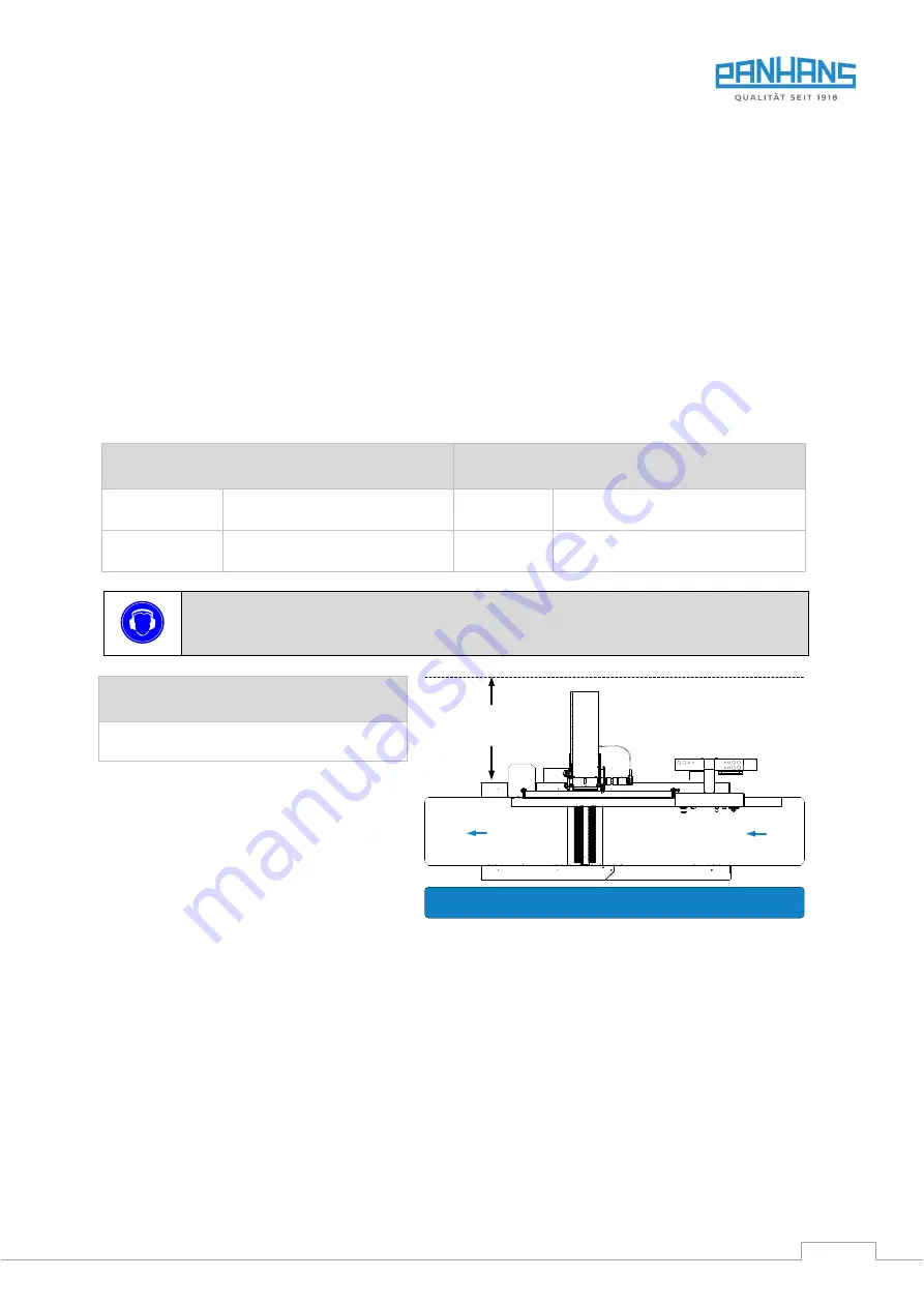
Figure 4: Working area


Working Area

Wall distance 

approx. 750 mm

Summary of Contents for 334|20

Page 1: ...Stauffenberg Kaserne Binger Str 28 Halle 120 DE 72488 Sigmaringen Tel 49 07571 755 0 E Mail info hokubema panhans de Web https hokubema panhans de Operating Manual Surface Planers and Jointers PANHAN...

Page 2: ...d Intended Use 12 4 1 2 Modifications and Conversions to the Machine 12 4 1 3 Residual Risks 13 4 2 Observe the Environmental Protection Regulations 14 4 2 1 Organisational Measures 14 4 2 2 Personnel...

Page 3: ...and OFF 28 9 1 1 Switching ON 28 9 1 2 Switching OFF 28 10 Machine Operation 29 10 1 Electrical Chip Removal Adjustment 29 10 2 Hollow and Pointed Joint Adjustment 29 10 2 1 Calibrate Hollow and Poin...

Page 4: ...the PANHANS Spiral Cutter Block 39 13 Troubleshooting 40 14 Maintenance and Inspection 41 14 1 Lubrication Instructions 41 14 2 Readjust Motor Brake 42 14 2 1 Checking the Adjustment 42 14 2 2 Replac...

Page 5: ...Figure 21 Activate angular adjustment 31 Figure 22 Adjusting angles 31 Figure 23 Auxiliary fence 32 Figure 24 Push block push handle 32 Figure 25 Planer guard TXF 1570 33 Figure 26 Guard setting for f...

Page 6: ...enance during maintenance servicing inspection repair and or during transport Apart from the operating manual and the legally binding accident prevention provisions applicable in the coun try and plac...

Page 7: ...hese instructions may result in personal injury Reference to the obligation to wear protective goggles Non observance of these instructions may result in personal injury Reference to the obligation to...

Page 8: ...intenance instructions In order to acquire the knowledge required to operate this machine the operator must ensure the following measures Product training for every operator also possible external per...

Page 9: ...delay and repaired if necessary For repairs only original spare parts may be used All protective safety and monitoring devices must be regularly checked and maintained by the operator Only instructed...

Page 10: ...ith main switch cutter block switch brake release switch height adjustment of the feed table and digital indicator is designed to be user friendly as it is easily accessible from the operating side an...

Page 11: ...ar delta starting and motor protection switch 1 grease gun hollow mouthpiece 2 suction nozzles 160 mm 1 Si Tec push block for safe dressing of short workpieces Hand push handle for self made push bloc...

Page 12: ...acturer Improper use can lead to danger to persons and to a defect or damage to the machine Only the manufacturer s original planing cutter blocks and replacement knifes according to EN 847 1 are perm...

Page 13: ...imilar Therefore wear safety shoes especially when transporting and setting down the machine Pay attention to the existing danger of cuts on the planing knifes Never reach into the running band saw bl...

Page 14: ...ng manual Operators must not wear open long hair loose clothing or jewellery including rings There is a risk of injury e g by getting caught or drawn in Observe the safety instructions and danger warn...

Page 15: ...allow a safe hand support push blocks are to be used The shape of the push block must be adapted to the workpiece Machine condition Check the machine for externally visible damage and defects at leas...

Page 16: ...otective devices These must be in the intended places and in perfect working order Defective guards must be replaced immediately Do not start planing until the motor tool has reached full speed Do not...

Page 17: ...able It is forbidden to be in Danger Zone 2 Figure above when the cutter block is running This ap plies equally to the operator and to any helper 2 Risk of kickback Risk of injury due to the work piec...

Page 18: ...HOKUBEMA Maschinenbau GmbH Graf Stauffenberg Kaserne Binger Str 28 Halle 120 DE 72488 Sigmaringen Germany Tel 49 0 7571 755 0 Fax 49 0 7571 755 2 22 Figure 3 Nameplate 5 2 Technical Features 2850 mm...

Page 19: ...ty The permissible workplace values can also vary from country to country However this information should enable the user to make a better assessment of hazard and risk 5 3 2 Noise Emission Values The...

Page 20: ..._PH_335 20_EN_07 22 docx 20 6 Dimensions 6 1 Front Top View Figure 5 Dimensions top side view Subject to design and dimensional changes 1587 2852 1097 1700 635 735 855 1320 1420 1540 Version 334 335 3...

Page 21: ...BA_PH_335 20_EN_07 22 docx 21 6 2 Side View Figure 6 Dimensions side view Subject to design and dimensional changes 379 479 599 Version 334 335 336 860 900...

Page 22: ...ransport 7 3 Installing the Machine A foundation is not required The floor must have a load bearing capacity corresponding to the weight of the machine Before placing the machine on the ground fit the...

Page 23: ...hing strap must be used for each lashing point All four lashing points must be tensioned individually on the loading area of the vehicle The pallet must also be secured against slipping Please note th...

Page 24: ...inals 23 and 24 of contactor K1M see wiring diagram Installation only by a qualified electrician The air speed must be set in such a way that with the extraction line connected and the tools stationar...

Page 25: ...sed electrician can a guarantee be given for the motor In the event of a complaint the electrician must confirm in writing that he has connected the machine in accordance with the regulations 7 8 Back...

Page 26: ...ew No Description No Description 1 Control panel details see section 8 2 6 Angle scale for fence 2 Fence 7 Hollow pointed joint setting 3 One hand lever for fence adjustment 8 Outfeed table adjustment...

Page 27: ...provides a better illustration of the respective operating elements Figure 14 Control panel surface planing jointing No Description No Description H Main switch U Move infeed table upwards M Cutter bl...

Page 28: ...F Figure 15 Control panel with main switch 9 1 1 Switching ON Turn the main switch H to position I Start cutter block with push button M The machine starts with automatic star delta switching 9 1 2 Sw...

Page 29: ...he digital indicator Important Hollow and pointed joint adjustment only when the control unit is switched on 10 2 1 Calibrate Hollow and Pointed Joint on the Digital Indicator If the adjusting screw S...

Page 30: ...Only if other cutter types are used and these are re sharpened it may be necessary to adjust the outfeed table via handwheel H Clockwise Direction upwards Counterclockwise Direction downwards In the s...

Page 31: ...djust an angle the auxiliary fence must first be folded down parallel to the table Figure 21 Activate angular adjustment Figure 22 Adjusting angles 1 For angular adjustment press both levers 1 and 2 t...

Page 32: ...ver disengages and push it back wards or forwards and release it at the desired position 10 4 4 Using the Auxiliary Fence For planing narrow workpieces or for joining work use the swivelling auxiliary...

Page 33: ...parallel to the tables and is automatically held in position Figure 26 Guard setting for flat planing Figure 27 Guard setting for edge jointing For several operations the workpiece is brought back ove...

Page 34: ...press the rightmost button Enter Figure 31 Calibrate chip removal 3 Figure 32 Calibrate chip removal 4 4 The mask shown in the picture above appears with the arrow symbol in the upper left corner 5 If...

Page 35: ...Zero point tab as shown in the picture above is activated 3 Then press the rightmost button Enter Figure 35 Calibrate angle 3 Figure 36 Calibrate angle 4 4 The mask shown in the picture above appears...

Page 36: ...334 410 mm Version 335 510 mm Version 336 630 mm Knock back the pressure bar segments using a hammer in combination with the brass wedge 3 included in the delivery or a piece of wood Please do not use...

Page 37: ...le for damage caused by a deviating or improper procedure 12 2 1 PANHANS Cutter Block Adjusting Devices The standard cutter block adjusting devices are already included in the scope of delivery when o...

Page 38: ...ck of the adjusting nut cor responds to 0 1 mm The blade projection on all thickness planers is 1 0 mm The adjusting nut 2 is to be turned back by 10 pitch points 3 Then insert the new resp sharpened...

Page 39: ...he torque spanner until it locks into place Only use the PANHANS service set for spiral cutter shafts to change and turn the cutting inserts The manufacturer is not liable for damage caused by a devia...

Page 40: ...efective Replace main switch Motor defective Replace motor V belt torn Replace V belt Emergency stop is locked Unlock emergency stop Motor no longer brakes in intended time 10 sec Brake pads are worn...

Page 41: ...ure its effectiveness The air velocity to the extraction system must be checked before the initial commissioning and after signif icant modifications Do not use the machine until these conditions are...

Page 42: ...ake is dragging or has been adjusted too much If the brake drags the readjustment made must be minimally returned again Danger of cutting Wear protective gloves when handling the knives or cutter bloc...

Page 43: ...t Loosen the nuts M on the angle plate W and press the motor block down A lever made from a piece of wood is very suitable for this purpose Then tighten the nuts M again Do not tighten the V belt R to...

Page 44: ...ock shaft made of continuous cut steel 3304 Strip Planer Knife 1505 Standard for 335 20 PANHANS Granat 510 x 35 x 3 mm standard quality for PANHANS Tradi tional Cutter Block shaft made of continuous c...

Page 45: ...1 litre resin dissolving concentrate 1 cleaning brush each of steel and brass 10 reversible carbide inserts 15 x 15 x 2 5 mm incl 5 screws Torx M6 x 15 mm 1 torque spanner and 2 bit inserts for assem...

Page 46: ...n laws in force at the place of use regarding the disposal of industrial solid waste toxic and hazardous waste Hoses and plastic parts as well as other components that are not made of metal must be di...

Page 47: ...Year of manufacture in the version provided complies with the following directives Machinery Directive 2006 42 EG EMC Directive 2004 108 EG The notified body 0392 DGUV Test Pr f und Zertifizierungsste...

Reviews: