background image


PVIQ™ CONNECTIVITY SYSTEM USER MANUAL V 1.0 


63 


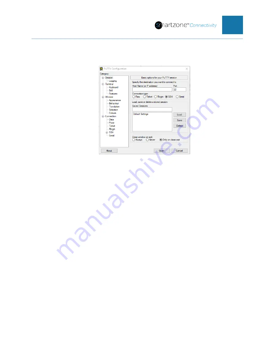
Logging in with Telnet via PuTTY 

1.  Open the PuTTY terminal emulation program. 


Figure 37: PuTTY Configuration Window 


2.   Select the Telnet radio button in the PuTTY Configuration window. 

3.  Type in the PViQ™ Connectivity PM IP address acquired from Appendix B 

process and leave all other settings as default. 

4.  Select 

Open

A terminal window will open, wait for the PViQ™ Panel to prompt for a 
“Username:” 

Default Username is: 

admin


Default Password is: 

panduit


5.  Enter the Username. Press 

Enter

6.  Enter the password. Press 

Enter

A screen similar to the below figure will appear. 

Summary of Contents for Smartzone PViQ Connectivity System

Page 1: ...PViQ Connectivity System User Manual...

Page 2: ...Installing Connecting PViQ Connectivity System to the Management Network 18 Initial Power Up of PViQ Connectivity System 18 Interacting with the PViQ Connectivity System 19 PViQ Connectivity System In...

Page 3: ...SNMP Management Configuration 61 Section 4 Accessing the PViQ Connectivity System Through the CLI 62 Introduction 62 Using the CLI 62 Telnet into the Panel Manager 62 Section 5 Accessing the PViQ Conn...

Page 4: ...idual Port Security Policy Method 82 Panel Learn Mode Method 84 Removing a Cross Connect Connection from the Patch Field 85 Individual Port Security Policy Method 86 Panel Learn Mode Method 87 Adding...

Page 5: ...I Cord Connection 102 Enhanced I Cord Connection Incorrect Switch Port 105 Fiber I Cord Connection 109 Fiber I Cord Disconnection 110 Fiber I Cord Guided Patching 111 Section 10 Safety Warranty Maint...

Page 6: ...Finding the PViQ Connectivity System IP Address 131 Finding the IP Address of the Panel Manager 131 Appendix C PViQ Connectivity CLI Commands 133 config 133 exit 135 ping 135 quit 136 reset 136 set 1...

Page 7: ...a Maintenance Mode Reset 157 Exiting Maintenance Mode 157 Appendix H Changing Your PC to Be a Standalone DHCP Server 159 Creating a Standalone DHCP Server 159 Reconfiguring the Ethernet Port on your P...

Page 8: ...Deployment General Guidelines 173 Secure Deployment for SNMPv3 Access Only 174 Secure Deployment for HTTPS Access Only 175 Best Practice for Password Complexity Strength 177 Best Practice for Secure P...

Page 9: ...ts that vary from ground by more than the maximum rating for that input Do Not Operate Without Covers To avoid electric shock or fire hazard do not operate this product with covers or panels removed D...

Page 10: ...tch field hardware The PViQ Connectivity Patch Panel and the PViQ Connectivity Fiber Tray There are several variants to each of these two types of patch fields PViQ Connectivity Patch Panel The Patch...

Page 11: ...timode with LC type data connections or MPO type data connections Figure 3 Standard PViQ Connectivity Fiber Tray with LC data connectors Intelligent Modules There are two types of intelligent modules...

Page 12: ...gle LAN port An expansion port extends management capabilities and power from the PM to 1 2 3 or 4 EMs The back of PM has a label showing the MAC Address of the Module Make a note of the MAC Address o...

Page 13: ...front of the panel There are two types of IU that may be attached to the patch panel The figures below show the IU for the Panel Manager and the IU for the Expansion Module Figure 7 PViQ Connectivity...

Page 14: ...onnected to the patch panel tray using the PViQ Connectivity Mounting Brackets Both the PM and EM use the same mounting bracket Mounting brackets including a built in securing screw are included with...

Page 15: ...sion Port Cable EPC The EPC is used to connect the PM to the EM and each successive EM When connecting the EPC make sure to connect the Data Out on the PM to the Data In on the EM Then connect the Dat...

Page 16: ...Patch Cords I Cord 2 PViQ Connectivity Enhanced Interconnect Patch Cords Enhanced I Cord 3 PViQ Connectivity Fiber Interconnect Patch Cords Fiber I Cord NOTE Advanced provisioning features of the Cop...

Page 17: ...LEDs also make it easy to identify the far end of I Cords that have been bunched together and groomed in advance by the installer The Enhanced I Cord has a 10 wire plug with separate contacts on each...

Page 18: ...the PViQ Connectivity System The Fiber Interconnect Patch Cord is available with LC or MPO fiber connectors and with single mode or multimode fiber Each Fiber Interconnect Patch Cord type is available...

Page 19: ...onnecting the PViQ Connectivity System into the network Initial Power Up of PViQ Connectivity System When power is first applied to a new PViQ Connectivity System a series of diagnostics and firmware...

Page 20: ...e CLI initiated using Telnet For details on using the PViQ Connectivity Web UI refer to Section 2 PViQ Connectivity Web User Interface in this document For details on using the IUs refer to Appendix G...

Page 21: ...h PViQ Connectivity Panel Appendix G Interacting with the PViQ Connectivity System Interface Units describes how the function keys work and some of the general tasks that can be accomplished with thes...

Page 22: ...aintenance Mode Location Mode Detached Mode Factory Mode These modes are defined in the following table Detailed information can be found later in this section Table 2 Mode Definitions Mode Meaning Se...

Page 23: ...he PViQ Connectivity Web UI the PViQ Connectivity Panel IU or the SmartZone Connectivity Software Module Location Mode Location Mode is used to identify where a specific panel resides within a facilit...

Page 24: ...us Indicator LED SYS remains solid green All other indicator LEDs are off The figure below shows the IU in Secure Mode NOTE The SYS LED for the PM will briefly flash amber every 10 seconds Figure 19 S...

Page 25: ...t associated with the violation to light solid red Figure 20 Secure Violation unauthorized patch cord inserted into a port Removing one end of a patch cord will also cause the far end port LED to ligh...

Page 26: ...ftware Modules place the PViQ Connectivity Panels Trays into MAC Mode This provides a visual reference on the panel and notifies the user that a change order is pending When the Web UI is used to perf...

Page 27: ...de In Learn Mode the System Status Indicator LED SYS is lit solid green The Mode Indicator LED MODE is amber The below figure shows the IU in Learn Mode Figure 23 Learn Mode Entering and Exiting Learn...

Page 28: ...cal functions and troubleshooting procedures CAUTION This section describes actions that can cause the PViQ Connectivity System database to be cleared losing all current configurations provisioning an...

Page 29: ...o locate specific PViQ Connectivity Panel Identifying Location Mode In Location Mode the System Status Indicator LED SYS will light solid green The MAC Mode and TRC Indicator LEDs are off The followin...

Page 30: ...de and return to Secure Mode use the CLI set mode command as shown below set mode x secure Where x is the offset number of the panel Mode Identification Summary The table below provides a quick refere...

Page 31: ...m is in the normal operating state Secure Mode with no Secure Violations the Port LED indicators are off that is the LEDs are not illuminated regardless of the presence of a patch cord Table 4 Port In...

Page 32: ...Flashing Green Move Add or Change MAC is pending on this port Waiting for insert Flashing Red Move Add or Change MAC is pending on this port Waiting for remove Solid Red ALL ports Panel is in Mainten...

Page 33: ...wsers The supported Web browsers are Mozilla Firefox Microsoft Edge Google Chrome and Apple Safari for desktops Google Chrome and Apple Safari for mobile devices Logging in to the Web Interface Open a...

Page 34: ...PViQ Connectivity System Only the Dashboard Patching and Alarms Pages refresh automatically The Network Page will automatically refresh during firmware updates only Login Page The Login Page appears...

Page 35: ...header is a table of attributes for the PViQ Connectivity Panel and the rack cabinet where it is located The default values are shown in the figure above You can change these attributes on the Network...

Page 36: ...ater in this document Security Policy This column provides the security policy that has been set on each port in the panel The column Security Policy provides the far end port or device port number th...

Page 37: ...lect a panel button to open a drop down menu that allows you to view any panel in the PViQ Connectivity System There may be 1 to 5 panels in a system Each system configuration must contain a PM panel...

Page 38: ...nel All PViQ Connectivity Panels Trays have 24 ports Panel Mode actual This read only field shows the current mode of the panel The panel can be in one of 8 different modes Secure Learn Detached Trace...

Page 39: ...NOTE Panduit recommends running only one trace at a time to avoid confusion Alarm Status actual This read only field provides the status of the alarm on this port The alarm status will be one of the f...

Page 40: ...vides name of the far end panel for a device Only far end PViQ Connectivity Panels may be customized by the user at this time To edit this field login to the Network Page of the far end panel If the f...

Page 41: ...ar end of the cable is connected to port 8 on panel 3 then this value would be 3 8 Set Security Policy Button Setting a security policy is typically used when a new patch cord has been added This butt...

Page 42: ...bout the current Security Policy set on this port and provides an option to clear this security policy Far End Panel expected This is the expected name of the panel that is at the far end of the patch...

Page 43: ...y Policy button when an expected connection is to be removed from the patch field Login to the appropriate PViQ Connectivity System and select the appropriate panel and port that the connection is to...

Page 44: ...ive in each panel If there are none on a given panel then there will be no summary line under that panel Following the summary line under each panel is a list of the current security violations in por...

Page 45: ...nd entry in the list is a description of the alarm The rest of the entries are descriptors for SNMP traps Track down where the alarm occurred by identifying the Rack Name Panel Name and port number Th...

Page 46: ...onnect 290 A PM or EM has been reconnected to the wing boards 295 A PM or EM has been disconnected from the wing boards 999 Unknown trap type Network Page From any page click the Network tab in the pa...

Page 47: ...ield automatically updates when a new version of firmware is installed on the PViQ Connectivity System The PViQ Connectivity Web UI is available in firmware version 02 00 00 or later System Name This...

Page 48: ...e System Name of the and vice versa Panel Mode This read only field automatically updates when the panel changes modes The panel could be in anyone of the 8 different modes Secure Learn Detached Trace...

Page 49: ...eld is for informational purposes only Changing this field will not change the panel type Shield Select Click Shield to open a pulldown menu that allows you to select the type of shielding shielded or...

Page 50: ...ct the day in the week in which daylight savings time will end DST Time Offset This is a user selectable pulldown menu that allows the customer to select the offset in time 1 Hour or 30 Minutes that w...

Page 51: ...nd key It is recommended to change this key to maintain data security on the system The PViQ Connectivity System ships with a default certificate and encryption key All systems have the same default e...

Page 52: ...s of firmware update success Retry Intervals This is a user selectable pulldown number that allows the customer to select the delay in minutes between retries As explained in the Max Retry section abo...

Page 53: ...ld that is automatically updated as the status changes during a firmware update to the PViQ Connectivity System Error Status This is a read only field that is automatically updated if any errors occur...

Page 54: ...lldown menu that allows the customer to select the refresh rate in minutes The refresh rate is defaulted to 720 minutes 12 hours The refresh rate is the rate at which the system will synchronize its t...

Page 55: ...he Save button you will lose the changes on the previous panel You must click the Save button before you select a different panel on the Network Page Cancel Button The Cancel button may be selected if...

Page 56: ...all pages in the PViQ Connectivity Web UI This page allows the entry of all the email attributes into the system so email alerts can be sent to individual emails Figure 35 Email Page Page Header Belo...

Page 57: ...red and maintained in the alarm log Trap Categories These are check boxes to enable or disable the type of alerts that will be sent to the recipient All alerts fall into one of these three categories...

Page 58: ...field Encryption Protocol Select The Encryption Protocol select button is a pulldown menu to select the encryption type used on the email server This pulldown has three options None SMTPS or STARTTLS...

Page 59: ...re not to be saved The Cancel button may also be selected to refresh the page NOTE any changes made on this page after the last save will be lost Users Page From any page click on the Users tab in the...

Page 60: ...being able to log into this PViQ Connectivity System If a user is not approved to log into the system user is setup to be able to log into the system but is not authorized yet a user s password has b...

Page 61: ...Web UI only NOTE To use the system with the SmartZone Software the user must have Telnet protocol enabled to run the CLI automated scripts to configure the system for SmartZone Software Save Button I...

Page 62: ...PVIQ CONNECTIVITY SYSTEM USER MANUAL V 1 0 61 Section 3 Simple Network Management Protocol SNMP SNMP Management Configuration For details on SNMP refer to the SmartZone Software User Manual...

Page 63: ...20 ports on five panels during any given session This section provides the following The basic procedure for initiating a CLI session The default login and password for the CLI Using the CLI Commands...

Page 64: ...TY Configuration window 3 Type in the PViQ Connectivity PM IP address acquired from Appendix B process and leave all other settings as default 4 Select Open A terminal window will open wait for the PV...

Page 65: ...gged into the PViQ Panel Refer to the CLI Commands list in Appendix C PViQ Connectivity CLI Commands for available commands NOTE For security purposes it is recommended to change the default password...

Page 66: ...he First Time For security reasons it is recommended to change the password upon login 1 Open a supported web browser Enter the IP address of the PViQ Connectivity System 2 The Login Page will appear...

Page 67: ...n username Figure 41 Users Page password 5 Click Save The default password for the admin username has been changed to the new password If the admin username password needs to change again perform thes...

Page 68: ...standard Administrator Privileges with Web UI Access only profile Any one of these access privileges may be changed from either the Web UI or Telnet through CLI commands User Accounts Add a user with...

Page 69: ...Users Page 2 Select Both HTTP or Telnet from the pulldown menu under Allowed Protocols on the specific user s line to change the access privileges for that user 3 Click on the Save button Delete user...

Page 70: ...vity Panel o The mechanical shape of each PViQ Connectivity Panel o The shielding of each PViQ Connectivity Panel Configure the PViQ Connectivity System for automatic change time for o Daylight Saving...

Page 71: ...es on each panel in a PViQ Connectivity System 1 Open a supported web browser Enter the IP address of the PViQ Connectivity System that is being configured 2 The Login Page will appear Enter the appro...

Page 72: ...of this panel from the Configured Mode pulldown menu a There are two modes to select from The default mode is Secure b The recommended mode is Secure i Secure mode any unauthorized changes in the pat...

Page 73: ...e this if the customer has a shielded panel and decides to populate it with unshielded minicom modules 13 Click on the Save button in the Actions section to save your changes Figure 45 Network Page pa...

Page 74: ...ge 6 Select the start month from the Start Month pulldown menu 7 Select the start week from the Start Week pulldown menu 8 Select the start day from the Start Day pulldown menu 9 Select the start time...

Page 75: ...Web UI will automatically log you out after 5 minutes of inactivity with the PViQ Connectivity System Changing fields is not consider activity with the PViQ Connectivity System until you click the Sa...

Page 76: ...er would select Static 6 If Static IP address mode is selected consult with your IT administrator to obtain the proper static IP Address to assign to this PViQ Connectivity System to obtain the Networ...

Page 77: ...tain the IP Address of the Primary Secondary and Tertiary NTP servers that the PViQ Connectivity System may connect to a Type in the designated addresses in the appropriate fields in this section b Th...

Page 78: ...The NTP server provides the UTC and the system must be set to an offset from the UTC to provide the local time b Example US Central Standard Time CST is 6 00 9 Click on the Save button in the Actions...

Page 79: ...more permanent and highest density network element such as the high speed switch is permanently cabled to the back of the PViQ Connectivity System with modular jacks PViQ Connectivity Patch Cords are...

Page 80: ...osts and cabling time as shown in the figure below Figure 50 Cross Connect Enterprise or Edge Solution Interconnect Interconnect configurations utilize PViQ Connectivity Interconnect Patch Cords to pr...

Page 81: ...ents and utilize higher density connections than other computing areas as shown in the figure below Figure 51 Interconnect Data Center or Edge Solution Interconnect Enterprise or Edge Solution The int...

Page 82: ...Patch Cords guides installers to the correct switch and panel ports for moves adds and changes The PViQ Connectivity System detects connections and disconnections made between the switch and PViQ Conn...

Page 83: ...uring Learn Mode act differently than ports that were explicitly provisioned in Secure Mode using Set Security Policy When in Secure Mode Learn Mode provisioned ports will automatically go back to Sec...

Page 84: ...eld is populated with Connected Both Ends c The Patch Cord Type field is populated with Cross Connect d The Panel or Device Name field is populated with the name assigned to the panel at the other end...

Page 85: ...e will appear 4 Select the panel from the Select a Panel pulldown menu 5 Select Learn in the Configuration Mode field from the pulldown menu 6 Click on the Save button to change the panel into Learn m...

Page 86: ...above the port will light amber and the system will provide a single audio beep followed quickly by turning both port LEDs green and two audio beeps indicating both ends are connected 12 Change all p...

Page 87: ...the following steps are completed 2 The Login Page will appear Enter the appropriate username and password The Dashboard page will appear 3 Select the Patching tab The Patching page will appear 4 Sele...

Page 88: ...rd page will appear Select the Network tab The Network page will appear 4 Select the panel from the Select a Panel pulldown menu 5 Select Learn in the Configuration Mode field from the pulldown menu 6...

Page 89: ...mode back to Secure mode For each panel in Learn mode select Secure in the Configuration Mode field from the pulldown menu NOTE You may have to log back into each system to change the panels back to S...

Page 90: ...ded connection is being added to 3 The Login Page will appear Enter the appropriate username and password 4 The Dashboard page will appear Select the Patching tab 5 The Patching page will appear 6 Sel...

Page 91: ...patch field This method is typically used when removing one or more individual connections in patch field The following steps are used to remove interconnect connections from a PViQ Connectivity Syst...

Page 92: ...is being removed from 2 The Login Page will appear Enter the appropriate username and password The Dashboard page will appear 3 Select the Network tab The Network page will appear 4 Select the panel f...

Page 93: ...System ports to network devices i e Ethernet Switch Server etc There are two methods to add fiber interconnect cables to the patch field The first method is through individual port security policy set...

Page 94: ...ity Policy button a The LEDs above the ports that the patch cord is plugged into will extinguish b The Panel Mode with go into MAC mode for a short while c Then Panel Mode will transition back to Secu...

Page 95: ...e populating your fiber interconnect cables in the patch field and the system will learn the connections as they are made However any connection that was in place and was a security policy violation w...

Page 96: ...wing step should be performed to clear a Security Violation that resulted from a cross connect patch cord being removed without authorization 1 If one or both ends of a cross connect patch cord were r...

Page 97: ...econnect that patch cord to the same port on the PViQ Connectivity System and to the same port on the network device The PViQ Connectivity System port will have the port LED light red 2 Then follow th...

Page 98: ...hould be connected reconnect that patch cord to the same port on the PViQ Connectivity System The PViQ Connectivity System port will have the port LED light red 2 Then follow the steps outlined in the...

Page 99: ...one software required to operate with the PViQ Connectivity System SmartZone Asset Software Module may be included to gain the full experience when connecting I cords into the system For details on cr...

Page 100: ...ded connection NOTE This may take 3 8 seconds depending on the switch Figure 55 PM IU and Port during a Guided Add far end connect On the PViQ Patch Panel the Port LED to which the cable should be con...

Page 101: ...demonstrates the steps of connecting an I Cord as they would occur if perfectly executed The procedure in this section demonstrates what would occur in a common failure scenario in this case a technic...

Page 102: ...o a flashing RED indicating an incorrect connection Figure 60 PM IU and Port during a Guided Add far end incorrect connect 4 Disconnect the far end of the I Cord from the incorrect port The MODE LED b...

Page 103: ...d port on the PViQ Patch Panel The MAC LED turns off the MODE LED changes to green briefly then the panel returns to Secure Mode if the MAC is complete on this panel The Port LED turns off Figure 65 P...

Page 104: ...so the LED of the Enhanced I Cord flashes green Figure 68 PViQ Enhanced I Cord during a Guided Add NOTE If the target panel is an EM the PM MAC will extinguish when the I Cord is removed from the Prov...

Page 105: ...should be connected begins flashing green Figure 71 Target Port during a Guided Add 4 Remove the Enhanced I Cord from the PM Provisioning Port and connect it to the target port on the PViQ Patch Pane...

Page 106: ...the provisioning process again Enhanced I Cord Connection Incorrect Switch Port The previous scenario demonstrates the steps of connecting an Enhanced I Cord as they would occur if perfectly executed...

Page 107: ...oning connect Also the LED of the Enhanced I Cord flashes green Figure 76 PViQ Enhanced I Cord during a Guided Add 3 Connect the far end of the Enhanced I Cord to an incorrect port on the switch The g...

Page 108: ...re 79 PM IU and Port during a Guided Add far end incorrect connect removed The LED of the Enhanced I Cord flashes green Figure 80 PViQ Enhanced I Cord during a Guided Add incorrect connection at the s...

Page 109: ...be connected begins flashing green Figure 83 Target Port during a Guided Add 6 Remove the Enhanced I Cord from the PM Provisioning Port The MODE LED turns off Figure 84 PM IU when MAC is Complete 7 Co...

Page 110: ...ctivity screen the patch port shows a single ended connection with a secure violation Figure 85 Target Port on First Connect of Fiber I cord to the PViQ Panel during and Add 2 Drag the desired fiber s...

Page 111: ...a MAC delete interconnect command to the patch panel The panel prompts by flashing the designated port LED red and displaying MAC mode on front panel to the desired switch port Figure 87 Designated Po...

Page 112: ...the connection cell located between the two fiber switch port cells Right click the connection cell and select PViQ I Cord from the drop down list Click Save to implement the change The SmartZone Ass...

Page 113: ...panel signals the end of the MAC by returning to Secure Mode The SmartZone Asset and Connectivity Software Modules trust that the far end of the I Cord is connected to the appropriate switch port and...

Page 114: ...maintenance or repairs or open the unit Do not work on the product or connect or disconnect cables during periods of lightning activity Ultimate disposal of this product should be handled according to...

Page 115: ...SYSTEM USER MANUAL V 1 0 114 Section 11 Support and Other Resources Accessing Panduit Support For live assistance go to the Panduit com website To access documentation and support services go to the P...

Page 116: ...e EPC Expansion Port Cable GUI Graphical User Interface HTTP Hypertext Transfer Protocol HTTPS Hypertext Transfer Protocol Secured I Cord PViQ Interconnect Patch Cord IM Intelligent Module IU Interfac...

Page 117: ...umentation send any errors suggestions or comments to Documentation Feedback cs panduit com When submitting your feedback include the document title part number edition and publication date located on...

Page 118: ...ted Jack Modules 24 per panel five panels if applicable sold separately Interface Units o One Panel Manager Interface Unit o Four Expansion Module Interface Units Five Mounting Brackets not required f...

Page 119: ...ith appropriate cable management installed for proper cable routing The PM can be placed at either the top or bottom of the system depending on need or preference NOTE The Expansion Modules EMs are co...

Page 120: ...the PViQ Connectivity System Figure 94 Alternate Acceptable Mounting Screws Jack Module Installation After the PViQ Connectivity Panel is secured to the rack or cabinet the next step is to install ter...

Page 121: ...on the individual panels The IUs attach to the front of the flat or angled patch panels and provide access to various operational modes The PViQ Connectivity Panels are shipped from the factory with a...

Page 122: ...port located on it The panels for the Expansion Modules will receive IUs that do not have this Provisioning Port Refer to the following figures to see the differences Figure 98 Panel Manager Interfac...

Page 123: ...he center of the PViQ Connectivity Panel Figure 100 Mounting Bracket step 1 2 Pivot the bracket until the tabs on the patch panel rest inside the slots of the mounting bracket Figure 101 Mounting Brac...

Page 124: ...lligent Modules Panel Manager PM Expansion Module s EMs The installation procedure is the same for both the PM and the EM However the PM must be installed in the patch panel or fiber tray containing t...

Page 125: ...he slot on the bracket and an audible click should be heard Figure 105 Bottom Latch Engagement Repeat the process for each of the modules ensuring that each is firmly locked into place before proceedi...

Page 126: ...the network or the daisy chain Up to 30 PMs may be daisy chained together The PViQ Connectivity System 12VDC power supply sold separately must be connected to the 12VDC power input on the back of each...

Page 127: ...that the EPC is not stretched or stressed in any way especially when using cable managers Connecting Multiple PMs Multiple PMs may be daisy chained together providing management access of additional p...

Page 128: ...xpansion Port out to EM Expansion Port in B EM Expansion Port out to EM Expansion Port in C Connection B repeated for an additional EM D PM LAN out to PM LAN in Attaching the Power Supply The PViQ Con...

Page 129: ...to the PM strain relief with a Pan Ty cable tie available separately as shown below Figure 110 Power Supply Cord Strain Relief Expanded View NOTE For standard Fiber Trays the strain relief is integra...

Page 130: ...Q PS12VDC C Universal PVQ PS12VDC UNI Label and Label Cover Installation PViQ Connectivity Panels should be labeled according to TIA EIA 606 A standards To meet this requirement the Ultimate ID Networ...

Page 131: ...l Four label covers are included with each PViQ Connectivity Panel NOTE Write on labels are not included with this patch panel per TIA EIA 606 A standard which states To maximize legibility all labels...

Page 132: ...located on MAC Address Label above the LAN Connectors on the back of the PM Figure 112 MAC Address on the PM 2 Download the pviqutil exe utility from the Panduit web site http www panduit com 3 Copy...

Page 133: ...N The second column is a list of the corresponding Media Access Control MAC addresses 6 Find the MAC address of the PM which you found in Step 1 in this list and note the associated IP address For exa...

Page 134: ...mponents and variables as shown below config contactname name Configures the contact name for this PViQ cluster The variable name is a 256 byte free format string config devicename name Configures the...

Page 135: ...5 to the entered name The variable name is a 256 byte free format string config rackposition 1 5 position Sets the Rack Position variable for a given panel 1 5 to the entered numeric position The var...

Page 136: ...The timeout time is specified in minutes Maximum value is 30000 minutes approximately 20 days config trapver 1 5 v1 v2 v3 Sets the Trap Version for traps sent to v1 v2c v3 trap receiver config usernam...

Page 137: ...N Only qualified technicians should perform these resets Level 6 7 and 8 resets will cause the PViQ database to be cleared losing all current configuration provisioning and patch field connectivity da...

Page 138: ...pplication offset offset port copper multimode singlemode fieldterm default Overrides the current application for an individual panel or reset the default value set paneltype shape offset angled flat...

Page 139: ...for various parameters within the system show config Displays all of the configuration parameters of the system show contactname Displays the designated Contact Name for the system show devicename Dis...

Page 140: ...PViQ panels Also displays whether or not the panel settings have been modified from the default settings show physloc Displays the current setting for the Physical Location show pmemail account Displa...

Page 141: ...parameter settings for the default User Name show topology Displays the current topology for the system start Starts the various updates and processes as shown below start email alert email address I...

Page 142: ...Q CONNECTIVITY SYSTEM USER MANUAL V 1 0 141 Stops email alerts initiated with the start command help List available parameters for a given command or lists all available commands For example config he...

Page 143: ...n the use To display the current configuration parameters PSH config ip Example 1 config ip To display and change the current modes of the panels PSH show mode Example 2 show mode In Example 2 all of...

Page 144: ...splay the current Firmware Revision PSH show fw Example 4 show fw NOTE The screen capture in Example 4 shows the hardware data for the PM labeled as PE 1 or Panel Element 1 The remaining elements are...

Page 145: ...PVIQ CONNECTIVITY SYSTEM USER MANUAL V 1 0 144 Example 5 show port...

Page 146: ...iQ Connectivity System Firmware files on that server and execute the standalone TFTP server If your network already has a TFTP server that could be used to perform a firmware update on the PViQ Connec...

Page 147: ...e s and place on your TFTP server a Example for standalone TFTP server place the files in i c tftp root 3 Make note of the file names that have been placed on the TFTP server a Example of firmware fil...

Page 148: ...k the Save button frequently during the below steps The following steps are used to configure the TFTP server and update the firmware on the PViQ Connectivity System 1 Open a supported web browser Ent...

Page 149: ...lay between the retries may help improve the chances of success If you want the system to delay between retrying firmware update select the number of minutes to delay between firmware update retries i...

Page 150: ...fer to Logging in with Telnet via PuTTY to log into the system using a Telnet terminal emulation program The following steps are used to perform a firmware update on the PViQ Connectivity System via t...

Page 151: ...version 02 00 00 NOTE Because some operating systems may convert uppercase letters to lowercase ensure that filename contains only lowercase letters 2 When the firmware update is finished the system...

Page 152: ...ned for Management alarms Category Code Trap Description Management 1 Firmware Update status has changed 999 Unknown trap type Alarm codes assigned for Security alarms Category Code Trap Description S...

Page 153: ...o a switch 45 I cord provisioning cord has failed to detect CDP 50 I cord has been disconnected from a switch 70 Report the switch info for the I cord that has been connected to a switch port 80 Singl...

Page 154: ...led and powered up and the system is in the Secure Mode state one way to interact with the panel itself is through the Interface Unit IU Function Keys located on the front of the IU The following sect...

Page 155: ...ion Key a second time TRC indicator will change to solid green and an audible acknowledgement beep will sound 3 If the port being traced was connected to another panel the far end patch panel will aut...

Page 156: ...e seconds check the following Ensure the Interface Unit is for a PM and not an EM Ensure the unit is getting power Ensure the PM module is fully inserted into the PViQ Connectivity Panel Tray 2 Releas...

Page 157: ...processor or exit maintenance mode Level 2 Reset all non host processors Level 3 Performs Level 1 and Level 2 resets together Level 4 Set IP configuration to DHCP factory default Level 5 Clear SNMP c...

Page 158: ...Reset Indication 2 When the desired reset level is reached release both Function Keys simultaneously Result The elected reset level indications will continue for approximately 5 additional seconds du...

Page 159: ...PVIQ CONNECTIVITY SYSTEM USER MANUAL V 1 0 158 The panel will also exit Maintenance Mode after a 30 minute period of inactivity...

Page 160: ...s sourceforge net projects dhcpserver 2 Install the open source DHCP Server 3 Select all the default setting when asked 4 On your PC change to the C Install DHCP Server IPV4 directory 5 Edit the OpenD...

Page 161: ...lone bat file and select Create Shortcut b Move that shortcut to the PC Desktop by drag and drop 7 You now have a Standalone DHCP Server on your PC but you cannot use it until you reconfigure your Eth...

Page 162: ...PVIQ CONNECTIVITY SYSTEM USER MANUAL V 1 0 161 Figure 120 Control Panel 2 In the Control Panel window select Network and Sharing Center...

Page 163: ...PVIQ CONNECTIVITY SYSTEM USER MANUAL V 1 0 162 Figure 121 Network and Sharing Center 3 Select Change adapter settings from the menu on the left...

Page 164: ...R MANUAL V 1 0 163 Figure 122 Change Adapter Settings 4 Right click Ethernet and select Properties Figure 123 Properties 5 Select Internet Protocol Version 4 TCP IPv4 you may need to scroll down Then...

Page 165: ...PVIQ CONNECTIVITY SYSTEM USER MANUAL V 1 0 164 Figure 124 Internet Protocol Version 4 TCP IPv4 Properties...

Page 166: ...rver addresses radio button then selects automatically 7 Enter the following details into the appropriate boxes a IP address 192 168 0 250 b Subnet mask 255 255 255 0 8 Leave the Default gateway Prefe...

Page 167: ...dress automatically on this wired port on the PC then you must rerun each of the above steps in this subsection before using this PC to connect to another PViQ Connectivity System in DHCP mode Connect...

Page 168: ...HCP serve will start serving up a 192 168 0 251 IP address to the PViQ Connectivity System Logging into the PViQ Connectivity System with a Standalone DHCP Server 1 Open a supported web browser Enter...

Page 169: ...to disable HTTP Some customers may not want the web interface The HTTP Web Server may be disabled to configure the Panel Manager to be in the same factory default mode as those shipped with firmware...

Page 170: ...assword Press Enter A screen similar to the example below displays Figure 130 Pan Shell CLI Ready Window 7 You are now logged into the PViQ Panel Manager Refer to the CLI Commands list in Appendix C P...

Page 171: ...TCP and UDP Ports used by the PViQ Connectivity System This guide lists all ports that may be used by the product based upon user configured settings Port TCP or UDP Service or Protocol Name RFC Serv...

Page 172: ...9 submission Email Notification client 6387 UDP Panduit PVIQ RPC Protocol Device discovery server Best Practices for Secure Configuration of PViQ To minimize the threat surface of a deployed product i...

Page 173: ...e customer s requirements Up to 10 SNMPv3 users may be configured SNMPv3 users may be managed using net snmp s snmpusm command or any available SNMPv3 software that is capable of managing SNMPv3 USM u...

Page 174: ...ault admin user cannot be deleted via the Telnet CLI SNMP Trap Notifications Use SNMPv3 trap receivers with authPriv users Note that SNMPv3 Trap Receivers are also provided SNMPv3 Agent access Email A...

Page 175: ...ure manner It assumes the integrator will use Telnet for bulk configuration and troubleshooting and SNMPv3 with a single SHA 1 AES 128 user for all other operations SNMPv3 Traps are also used Use Teln...

Page 176: ...encrypted Because Telnet does not provide confidentiality it is recommended that Telnet access only be used in exceptional situations such as bulk re configuration or troubleshooting Secure Deploymen...

Page 177: ...additional certificate validation requirements Click Choose File and select the Certificate Key file Click Save to upload the certificate Reboot the PViQ Panel Manager to verify the new certificate is...

Page 178: ...patch field front of the panel is intended to provide security alerts for the patch cable connections Care should be taken for unused panel ports Use a RJ45 lock out device to block the panel ports P...

Page 179: ...Level 3 reset Level 7 Reformat the entire file system including clearing the database followed by a Level 3 reset Level 8 Reset firmware image to factory default followed by a Level 7 reset All firmw...

Reviews: