background image

AT-OME-MS52W

97

Configuration and Management Interfaces

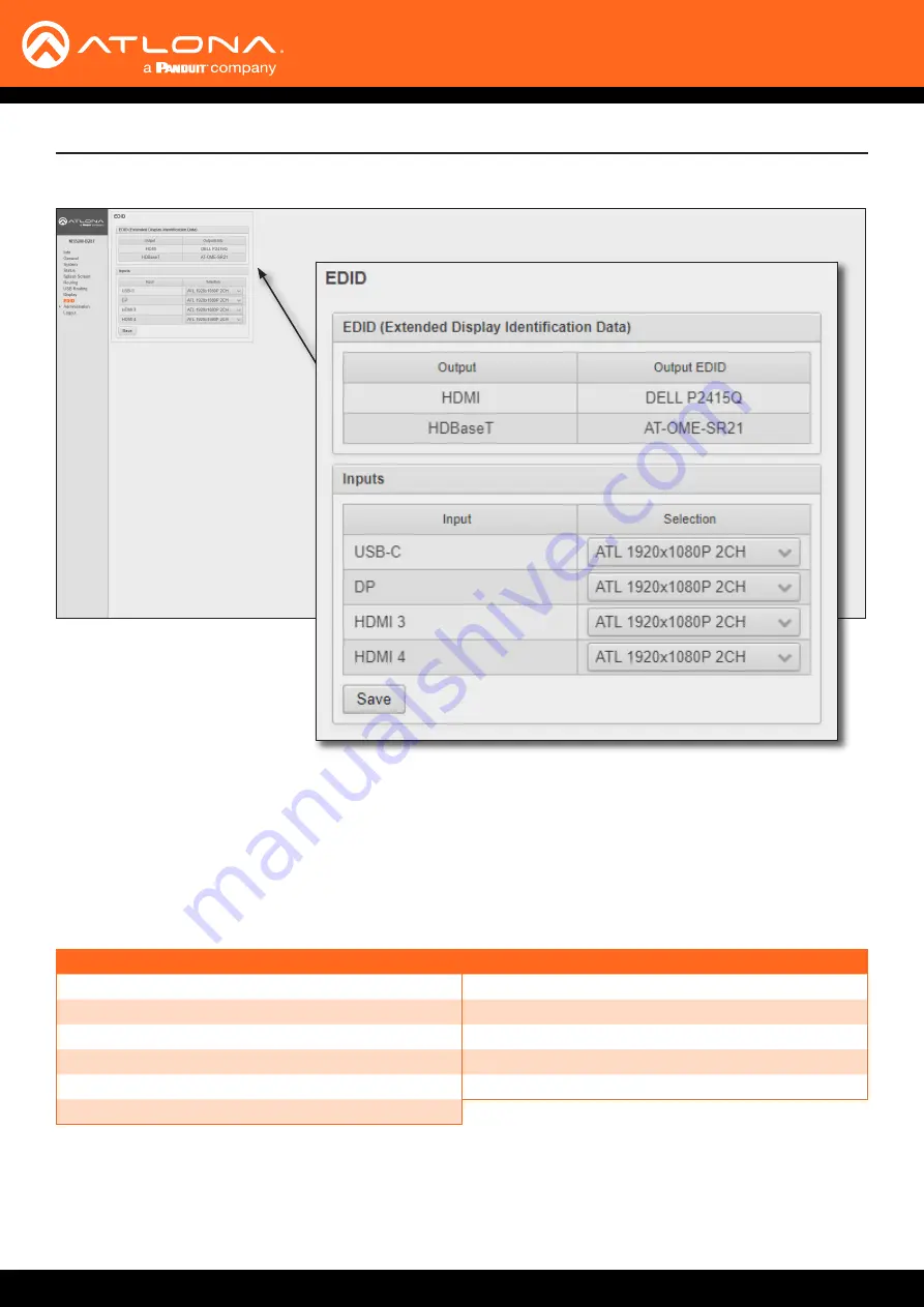
EDID page

EDID

EDID (Extended Display Identification Data)


Displays the EDID assigned that is being used by each output.  Press the 

Save

 button to save the EDID to a file.

Inputs


The 

Input

 column displays each of the inputs on the AT-OME-MS52W.  Click the drop-down list, under the 

Selection


column, to select the desired EDID to be used.  The table below lists the available EDID presets.


The table below provides a listing of available EDID presets.

EDID listing

4K60 2CH

1366x768@60 2CH

4K30 2CH

1280x800p60 2CH

4K30 4:4:4 2CH

1280x720p60 2CH

1920x1200p60 2CH

1024x768p60 2CH

1920x1080P 2CH (factory-default)

800x600p60 2CH

1600x900p@60 2CH

Save


Click this button to commit changes.

Summary of Contents for ATLONA Omega AT-OME-MS52W

Page 1: ...AtlonaManuals Switchers AT OME MS52W Multi format 5x2 Matrix Switcher for HDMI USB C DisplayPort and HDBaseT with USB and Wireless Link 4K UHD...

Page 2: ...AT OME MS52W 2 Version Release Date Notes 1 Jul 2020 Initial release Version Information...

Page 3: ...ct go to http atlona com registration Sales Marketing and Customer Support Welcome to Atlona Operating Notes Main Office Atlona Incorporated 70 Daggett Drive San Jose CA 95134 United States Office 1 8...

Page 4: ...s New Products 10 years from proof of purchase date for hardware electronics products purchased on or after June 1 2013 3 years from proof of purchase date for hardware electronics products purchased...

Page 5: ...cts or states do not allow the exclusion or limitation of relief special incidental consequential or indirect damages or the limitation of liability to specified amounts so the above limitations or ex...

Page 6: ...t block any ventilation openings Install in accordance with the manufacturer s instructions 8 Do not install or place this product near any heat sources such as radiators heat registers stoves or othe...

Page 7: ...22 Login Registration 22 Logging in after registration 23 Setting the System Date and Time 24 Automatic Adjustment 24 Setting Local Date and Time 25 Using an NTP Server 25 Selecting the Input 26 Swit...

Page 8: ...hanging the Password 77 Configuration and Management Interfaces 78 Web Server 78 Login Register page 78 Login page 79 Info page 80 General page 81 System page 82 Status page 85 Splash Screen page 86 R...

Page 9: ...0 and USB C interfaces for three host PCs plus two peripheral ports for devices such as a camera microphone speakerphone or keyboard and mouse Introduction Features Package Contents 5 2 AV matrix swit...

Page 10: ...Connect a USB cable from each of these ports to host computers 2 USB HUB Connect up to two USB devices e g mouse keyboard etc to these ports These ports provide 2 5 W per USB device interface 3 OUT 1...

Page 11: ...for audio de embedding Refer to Audio page 12 for wiring information 5 INPUT DisplayPort Connect a DisplayPort device to this port 6 INPUT HDMI Connect an HDMI cable from each of these ports to a UHD...

Page 12: ...3 16 5 mm of insulation from each of the wires 3 Insert the wires into correct terminal using the included 3 pin captive screw connector 4 Attach the 3 pin connector block to the RS 232 port on the AT...

Page 13: ...C1 and C2 are set to the Normally Open NO state C2 COM C1 The TRIGGER I O port allows voltage controlled devices such as an occupancy sensor to be connected to the AT OME MS52W Use the included 4 pin...

Page 14: ...e Core Shielding CAT5e CAT6 CAT6a CAT7 Solid UTP unshielded N A STP shielded 3 Connect a USB C cable from a source to the USB C 1 port 4 Connect a DisplayPort cable from a source to the DP IN 2 port 5...

Page 15: ...rmation 12 OPTIONAL Connect the relay leads from the control motors of the projection screen blinds or curtains to the relay outputs to the RELAY port using the included 3 pin captive screw connector...

Page 16: ...rnet LAN Laptop Tablet BYOD Laptop Laptop AT HDVS CAM USB 1 0 X Z o o m F 1 6 F3 0 f4 7m m f 4 7 m m 1 0 X Z o o m F 1 6 F 3 0 f 4 7 m m HDMI USB RS 232 USB Wireless Antennas included POW ER SHO W IP...

Page 17: ...P OUT L R RESET IP MODE MIRACASTTM 1 2 1 If a display device is unavailable use the following procedure to obtain the IP address of the AT OME MS52W Getting the IP Address without a Display 1 Make su...

Page 18: ...is occurs refer to Auto IP Mode page 18 for more information Auto IP Mode If the AT OME MS52W is unable to detect a DHCP server within 15 seconds then the unit will use a self assigned IP address with...

Page 19: ...inistration Networking 4 Under the Ethernet window group click the Mode drop down list to select DHCP Static or Factory Static If set to Static the IP Network Mask Gateway fields can be modified If se...

Page 20: ...flash The LED indicator will flash three times to indicate that the unit has been reset to factory default settings POWER SHOW IP DP HDMI 3 HDMI 4 BYOD USB C USB HOST 2 1 USB HUB OUT 1 OUT 2 AT OME MS...

Page 21: ...3 HDMI 4 BYOD Solid blue The input is the currently selected active input Off The input is not active IP MODE Flash green 4x Flashes four times to indicate that the unit is being set to DHCP mode Ref...

Page 22: ...r more information 3 Enter the desired username in the User field In the example below the username admin is used 4 Enter the desired password in the Password field IMPORTANT The password must contain...

Page 23: ...nter the correct username and password in the respective fields 3 Click the Login button Logging in after registration NOTE If using a secure connection click the Secure Login button 4 The Info page w...

Page 24: ...ion 2 Click System in the side menu bar 3 Under the Time window group click the here link to launch a web browser and obtain the current UTC Both the current local time and date will be set Setting th...

Page 25: ...functioning correctly then the date and time will be set automatically However the local time will need to be set 1 Login to the web server Refer to Logging in to the Web Server page 22 for more infor...

Page 26: ...ection window group click the desired input POWER SHOW IP DP HDMI 3 HDMI 4 BYOD USB C USB HOST 2 1 USB HUB OUT 1 OUT 2 AT OME MS52W USB USB USB USB USB 4 OUTPUT LAN DC 24V 3 2 INPUT USB AUDIO WiFi AUX...

Page 27: ...to the Web Server page 22 for more information 2 Click Routing in the side menu bar 3 Click the Switching Mode drop down list and select Matrix Mode IMPORTANT When the AT OME MS52W is set to Matrix M...

Page 28: ...T port 6 Click the Matrix Mode HDBaseT Source drop down list and select the input to be routed to the HDBaseT OUT port 7 Matrix Mode configuration is complete NOTE If the input for Matrix Mode HDBaseT...

Page 29: ...ed static input will be removed from the auto switching pool For example if the HDMI IN 3 port is specified as a static input then auto switching will skip this port when auto switching Matrix Mode w...

Page 30: ...atic source This source will be routed to the output selected in the Matrix Mode Static Output drop down list In this example the source connected to the Display port input will be output to the HDMI...

Page 31: ...ic route 4 Click the AutoSwitch checkbox to remove the check mark to disable auto switching Note that if the previously active input is no longer available that it will fallback to any available input...

Page 32: ...uired that both USB host ports be connected to host devices 2 Login to the web server Refer to Logging in to the Web Server page 22 for more information 3 Click USB Routing in the menu bar 4 Click the...

Page 33: ...t devices then the AT OME MS52W will set the last connected USB host device as the active USB host Use the procedure below to enable Follow USB mode 1 Connect the host computers to the USB host ports...

Page 34: ...the AT OME MS52W will automatically switch to the USB host port that was connected last 5 Follow USB configuration is complete In this mode a video input can be paired with USB 1 USB 2 or a remote US...

Page 35: ...1 0 X Z o o m F 1 6 F3 0 f4 7m m f 4 7 m m 1 0 X Z o o m F 1 6 F 3 0 f 4 7 m m PO WE R SH OW IP DP HD MI 3 HD MI 4 BY OD US B C US B HO ST 2 1 US B HU B OU T 1 OU T 2 AT OME MS52W USB USB Figure 1 1...

Page 36: ...server Refer to Logging in to the Web Server page 22 for more information 2 Click Splash Screen in the side menu bar Device Operation 3 The Splash Screen window group has several settings Note that t...

Page 37: ...AT OME MS52W when using a wireless connection version Displays the Master Firmware version password Displays the Access Point password when the AT OME MS52W is configured as an Access Point If configu...

Page 38: ...just the horizontal centering of the panel The default value is 0 center Positive values will shift the panel to the right Negative values will shift the panel to the left Adjusting the Y Offset does...

Page 39: ...l be displayed on top of the splash screen Device Operation An example of metadata is shown below 3 Click the Save button at the bottom of the Splash Screen window group to commit changes To hide the...

Page 40: ...be displayed as part of any text field on the splash screen by inserting the password tag as part of a text string For example To begin your presentation connect using the SSID and enter the followin...

Page 41: ...ing in to the Web Server page 22 for more information 2 Click Splash Screen in the side menu bar 3 Under the Images window group click the Enable Image Rotation checkbox Device Operation 4 Click the I...

Page 42: ...o be changed IMPORTANT Custom images should not exceed 1920 x 1080 All common image types such as JPG BMP PNG TIF GIF are supported 4 Select the new image file and click the Open button on the dialog...

Page 43: ...Not Supported HTML5 Relative absolute references Dynamic images e g animated GIF files CSS PHP JavaScript ASP client server side processing Downloading the default splash screen 1 Login to the web se...

Page 44: ...d can be used as a starting point when creating a custom HTML splash screen The example below is a partial listing of the HTML code within the default HTML file NOTE When creating an HTML splash scree...

Page 45: ...in to the web server Refer to Logging in to the Web Server page 22 for more information 5 Click Splash Screen in the side menu bar 6 Under the Splash Screen window group click the Type drop down list...

Page 46: ...n in the side menu bar 3 Click the Type drop down list and select HTML 4 Under the Splash Screen window group click the Reset button Resetting the HTML Splash Screen IMPORTANT The Reset Reset HTML but...

Page 47: ...tion the AT OME MS52W can be configured as a wireless access point AP The addition of a built in firewall provides filtering of outbound traffic from WAP to Ethernet When configured as an Access Point...

Page 48: ...password credential is desired 8 Click the Hide Password on OSD checkbox to prevent the WiFi Password field from being displayed 9 Click the Rotate WiFi Password checkbox to allow the AT OME MS52W to...

Page 49: ...DNS Mode drop down list and select the desired mode 16 To commit changes click the Save button located under the Save window group Feature Description Use default DNS Servers Uses the default DNS prov...

Page 50: ...w group click the Mode drop down list and select Access Point 4 Click Firewall Mode drop down list and select the desired option Setting Description None default Select this option to disable the fire...

Page 51: ...drop down list and select Connect to WiFi 4 Click the Preferred Gateway drop down list and select the desired gateway When set to Connect to WiFi mode the AT OME MS52W can only be accessed though the...

Page 52: ...ist and click the OK button to accept the selection or click Cancel to return to the WiFi window group Device Operation 7 Enter the password for the wireless network in the Password field 8 Click the...

Page 53: ...ng table provides a description of status messages State Description Connected The AT OME MS52W is connected to the wireless network Not Connected Unsuccessful connection Check to make sure the passwo...

Page 54: ...ier is held in the Name field under the General tab The AT OME MS52W copies the Name field to the Derived field converting the characters to lowercase The Derived field then becomes the SSID 1 Login t...

Page 55: ...to access the LAN A full explanation of the 802 1X protocol is beyond the scope of this manual However the illustration below shows the basic architecture E t h e r n e t E A P O L E A P E A P E t h...

Page 56: ...n server which will process the credentials For example if foo authserv com is entered then this identifies AUTHSERV as the RADIUS authentication server 6 Enter the password in the Password field 7 Cl...

Page 57: ...ge 22 for more information 2 Click Administration Networking in the side menu bar 3 Under the WiFi window group click the 802 1x Security Enable check box 4 Enter the server port number and the secret...

Page 58: ...iOS Devices 1 Select the BYOD input on the AT OME MS52W 2 On the iOS device go to Settings Wi Fi 3 Select the network to which the AT OME MS52W is connected or join its access point The example below...

Page 59: ...on the screen will also be rotate 90 degrees 9 Close the Control Center by either swiping down or pressing the Home button AirPlay is only supported on Mountain Lion 10 8 or later To determine if Air...

Page 60: ...rroring Click the AirPlay icon in the menu bar and select the desired display to be mirrored Extending Click the AirPlay icon and select Use As Separate Display from the list of displays to extend the...

Page 61: ...t of available devices will be displayed on the right hand side of the screen Select the AT OME MS52W hostname from the list 1 Right click on the Windows Desktop and select Display Settings from the p...

Page 62: ...n list 7 Click the x in the upper right corner of the Casting tab to dismiss this dialog When Chrome is casting the icon will appear in the upper right portion of the menu bar Clicking this icon will...

Page 63: ...This port accepts a 3 5 mm mini stereo cable 2 Login to the web server Refer to Logging in to the Web Server page 22 for more information 3 Click Administration Audio in the side menu bar 4 Click the...

Page 64: ...ehaves as a type of beacon indicating the available AT OME MS52W units within the local vicinity of an AirPlay device 1 Connect the Bluetooth adapter to the AUX port on the AT OME MS52W 2 Login to the...

Page 65: ...N code will randomly change every five minutes by default This value can be set from 10 seconds to five hours This provides a level of security preventing unauthorized users from accessing the AT OME...

Page 66: ...ed only for about 10 seconds If the PIN code is not entered within the time interval then the PIN code will be removed from the screen The example below shows an AirPlay device prompting for the PIN c...

Page 67: ...For example if another connection is made within 20 seconds after the nth connection then the same PIN code will be used to connect to the system 1 Login to the web server Refer to Logging in to the W...

Page 68: ...WiFi Refer to Wireless Configuration page 47 for more information 3 Click Administration Moderator in the side menu bar 4 Under the Moderator window group click the Enable checkbox If this checkbox ha...

Page 69: ...will be disabled In the example below Brenda s iPhone is now the active casting device and shown on the display device 7 Click the Allow button next to another device to make that device the active c...

Page 70: ...g device Active casting device Once a device has been kicked it will no longer appear in the Users table In the example below the device Andrew s iPhone has been removed from the Users table 9 To reco...

Page 71: ...ence of either a video signal on any of the physical inputs or a casting device The Auto Power Off Timer interval must expire before the display is turned off AutoSwitch must also be enabled for this...

Page 72: ...MS52W 72 Device Operation 5 Click the Auto Power Off Timer drop down list and select the desired time interval This is the amount of time that must elapse before the display is turned off 6 Setup is c...

Page 73: ...u bar 3 Under the Control window group make sure that the AutoSwitch checkbox is checked This feature must be enabled 4 Click the Display Control Method drop down list and select Active Video Presence...

Page 74: ...ntrol Method drop down list and select Occupancy Sensor 4 The Trigger I O window group will be displayed along with two checkboxes Enable Trigger On and Enable Trigger Off Check the Enable Trigger On...

Page 75: ...formation 2 Click Display in the side menu bar 3 Click the Display Control Method drop down list and select Day and Time 4 The Time Display Control window group will be displayed 5 Click the Start Tim...

Page 76: ...order for this feature to work the AT OME MS52W must be set as an Access Point Refer to Access Point Mode page 47 for more information 1 Login to the web server Refer to Logging in to the Web Server p...

Page 77: ...w group click the Change button 4 The Change Password admin dialog box will be displayed Enter the new password in the Password field Make sure to delete all the asterisks masks in this field before e...

Page 78: ...ures Refer to Logging in to the Web Server page 22 for more information This page is displayed when the AT OME MS52W web server is launched for the first time Web Server Login Register page User Enter...

Page 79: ...this field The username is admin Password Enter the password in this field The default password is Atlona It is recommended that the password be changed Refer to Changing the Password page 77 for mor...

Page 80: ...Version The version of firmware Firmware Version The version of firmware that the AT OME MS52W is running Always make sure to check the AT OME MS52W product page on the Atlona web site for the latest...

Page 81: ...ithin the OSD Derived This field will automatically be populated by the AT OME MS52W based on the information provided in the Name field This field provides a computer friendly name used by the SSID I...

Page 82: ...from the unit Factory Reset Click the Reset button to reset the AT OME MS52W to factory default settings Resetting to factory default setting may take up to five minutes to complete Refer to Resetting...

Page 83: ...are Version The version of MCU firmware that the AT OME MS52W is running Always make sure to check the AT OME MS52W product page on the Atlona web site for the latest version of firmware Firmware Chec...

Page 84: ...eadable by the AT OME MS52W Upload Click this button to upload the configuration file to the AT OME MS52W Both the Download and Upload button are useful to save and load different configurations and o...

Page 85: ...n and Management Interfaces Status page Status This page provides a information about the current state of the AT OME MS52W such as IP information memory usage casting devices active sources date time...

Page 86: ...down position of the overlay panel on the screen A value of 0 vertically positions the panel in the center of the screen Positive values move the panel down Negative values move the panel up Title Th...

Page 87: ...ide the text in this column Column 2 The text positioned in the right hand column The default text is Connect wirelessly Connect the Wi Fi network entercode and enable AirPlay Google Cast or Miracast...

Page 88: ...ge with a custom image Reset Splash Images Click the Reset button to set the splash screen images to the factory default images Enable Image Rotation Click this check box to instruct the AT OME MS52W...

Page 89: ...es window groups USBC DP HDMI3 HDMI4 BYOD Click the desired button to select the active input Matrix Switch Click this drop down list to select the desired matrix mode Refer to Switching Modes page 27...

Page 90: ...t which USB ports are connected to a host device If all USB host ports are connected to host devices then the AT OME MS52W will set the last connected USB host device as the active USB host Use the pr...

Page 91: ...power on when an active source is detected This applies to either physical source connections or casting The Auto Power Off Timer must expire before the power off command is sent Active Video Presence...

Page 92: ...t elapse after the display control on command is sent before the display power off command can be sent This feature is used to prevent a power off command from being sent while the lamps are warming u...

Page 93: ...Relay Pulse Duration Click this drop down list to select the desired pulse duration for the relay Some devices may require different time intervals to recognize a state change Range 1 to 10 seconds T...

Page 94: ...g both ports the RS 232 settings must be identical Setting Description Baud rate Sets the baud rate The following options are available 9600 14400 19200 38400 57600 115200 Data bit Sets the number of...

Page 95: ...s section is only available when the Control Type is set to either RS 232 or IP Manufacturer Click this drop down list to select the display manufacturer If the display device being controlled is not...

Page 96: ...ist Display Commands Once a device is selected the ON OFF Volume Volume and Mute fields will be populated with the correct information for that device If a device is not listed enter the appropriate c...

Page 97: ...the inputs on the AT OME MS52W Click the drop down list under the Selection column to select the desired EDID to be used The table below lists the available EDID presets The table below provides a li...

Page 98: ...AT OME MS52W 98 The Telnet page provides an emulated terminal for entering commands Administration Telnet page Configuration and Management Interfaces...

Page 99: ...this feature will have no effect Users This table lists all users which are casting using the AT OME MS52W Up to four users can be hosted at one time but only one can be displayed at a time Devices wi...

Page 100: ...ing page General Ethernet MAC Address Displays the MAC address of the AT OME MS52W Mode Click this drop down list to select the desired IP mode Setting Description DHCP Select this option to have a DH...

Page 101: ...his field This field can only be changed when Mode is set to Static DNS Server 1 DNS Server 2 Enter the DNS server addresses in the DNS Server 1 and DNS Server 2 fields If the AT OME MS52W will be use...

Page 102: ...to connect the AT OME MS52W to the specified SSID of a wireless host Disabled Select this mode to disable Wi Fi on the AT OME MS52W SSID The SSID assigned to the AT OME MS52W The SSID name can be chan...

Page 103: ...ME MS52W DNS Mode Click this drop down list to select the desired DNS mode DNS Server 1 DNS Server 2 Enter the DNS server addresses in the DNS Server 1 and DNS Server 2 fields If the AT OME MS52W will...

Page 104: ...or WiFi not both For example if Ethernet is selected then the AT OME MS52W can only be accessed from the same network over Ethernet However it should be noted that casting is supported on both interfa...

Page 105: ...ed DNS Server 1 DNS Server 2 These fields cannot be changed 802 1x Security Enable Click this checkbox to enable 802 1x authentication mode When enabled the Radius Server Radius Port and Radius Secret...

Page 106: ...wnloaded in a zip file Debug logs are used by Atlona Technical Support Engineers to identify functionality issues 1 Click Debug on the side menu bar 2 Click the Downloads Logs button to display the Sa...

Page 107: ...age allows the default password to be changed 1 Click the Change button to display the Change Password dialog box 2 Enter the new password in the Password field 3 Re enter the same password in the Rep...

Page 108: ...led When this feature is enabled username and password credentials will be required at the beginning of the Telnet session Enable Whitelisting Click this check box to enable whitelisting Whitelisting...

Page 109: ...efer to Refer to AirPlay Bluetooth Discovery page 64 for more information Airplay Miracast P2P PIN Click this check box to allow the ability to add randomized PIN codes when connecting using AirPlay A...

Page 110: ...w the hostname of the casting device on the splash screen Lock Power Button Check this box to enable or disable the locking of the POWER button on the front panel Locking this button will prevent acci...

Page 111: ...ces on a web page to be requested from another domain Resources can include stylesheets CSS scripts and other embedded elements Upload Click this button to upload the latest MCU firmware to the AT OME...

Page 112: ...page lists beta features which are currently in the pre release testing stage It should be noted that these features may not function reliably Features listed under this window group can change betwe...

Page 113: ...ch input Master Volume Click and drag this slider to adjust the output volume Output is adjustable from 80 to 0 dB HDMI 3 HDMI 4 USB C DP Click these drop down lists to select the desired audio input...

Page 114: ...ment Interfaces Administration Event Viewer page This page displays a dynamic list of events returned in JSON format The image below shows a list of sample events This page is useful for monitoring ev...

Page 115: ...nformation 4 Click System in the side menu bar Requirements AT OME MS52W Firmware files Computer on the same network as the AT OME MS52W 5 Under the Firmware window group click the Upload button 6 Bro...

Page 116: ...completed the AT OME MS52W will automatically reboot and the following message will appear at the top of the screen 9 Click the message or press the ESC key to return to the Login screen Enter the lo...

Page 117: ...ll rack ear sold separately to one side of the AT OME MS52W using the included screws 2 Attach the included longer rack ear sold separately to the opposite side of the AT OME MS52W using the included...

Page 118: ...SB PO W ER SH O W IP D P H D M I 3 H D M I 4 BY O D U SB C U SB H O ST 2 1 U SB H U B O U T 1 O U T 2 A T O M E M S 5 2 W USB USB P O W E R S H O W I P D P H D M I 3 H D M I 4 B Y O D U S B C U S B H...

Page 119: ...1 O U T 2 A T O M E M S 5 2 W USB USB P O W E R S H O W I P D P H D M I 3 H D M I 4 B Y O D U S B C U S B H O S T 2 1 U S B H U B O U T 1 O U T 2 A T O M E M S 5 2 W USB USB Countersink bevel Flat Sur...

Page 120: ...nal gain 20 dBu headroom Frequency Response 20 Hz to 20 kHz 0 5 dB THD N 0 009 20 Hz to 20 kHz SNR 94 dB 1 kHz zero clipping 0 dBFS unweighted Sample Rate 32 kHz 44 1 kHz 48 kHz 88 2 kHz 96 kHz 176 4...

Page 121: ...nnel HDBaseT OUT 1 RJ45 LAN 1 RJ45 10 100 1000 Mbps DC 24V 1 4 pin DIN locking Indicators and controls Output Indicators USB C DP HDMI 3 HDMI 4 BYOD 5 LED blue OUT1 HDMI 5 LED blue OUT2 HDBaseT Contro...

Page 122: ...ams Device 3 89 1 77 Certification Device CE FCC Power CE FCC UL 1 18 Gbps supported for HDMI 2 0 output 2 HDMI output supports 4K UHD 50 or 60Hz with 4 4 4 chroma sampling HDBaseT output supports 4K...

Page 123: ...names and trademarks or registered trademarks are the property of their respective owners Pricing specifications and availability subject to change without notice Actual products product images and o...

Reviews: