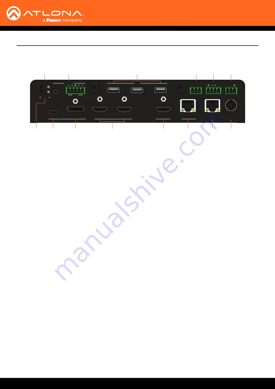
AT-OME-MS52W
11
POWER
SHOW IP
DP
HDMI 3
HDMI 4
BYOD
USB-C
USB HOST
2
1
USB HUB
OUT 1
OUT 2
AT-OME-MS52W
USB
USB
USB
USB
USB
4
OUTPUT
LAN
DC 24V
3
2
INPUT
USB
AUDIO
WiFi
AUX
IN
RS-232
RX TX
RELAY
TRIGGER I/O
COM
C1
C2
P
OUT
L
R
RESET
IP MODE
MIRACAST
TM
1
2
1
Panel Description
Rear
Panel
1 IP MODE
Press and release this button to set the IP mode of
the AT-OME-MS52W. Refer to
for more information.
2 RESET
Press and release this button to reset the unit to
factory-default settings. Refer to
Factory-Default Settings (page 20)
information.
3 INPUT (USB-C)
Connect a USB-C cable from this port to a USB-C
source.
4 AUDIO
Connect a 3.5 mm mini-stereo cable from an analog
audio source to the
IN
port, to provide optional
embedded analog audio on the output. Connect
a balanced stereo audio output device to the
OUT
port using the included captive screw block for audio
de-embedding. Refer to
information.
5 INPUT (DisplayPort)
Connect a DisplayPort device to this port.
6 INPUT (HDMI)
Connect an HDMI cable from each of these ports to a
UHD/HD source.
7
USB HUB
Connect the included WiFi antenna to these ports.
The
MIRACAST
port is reserved for the Miracast
casting protocol. The
AUX
port is reserved for system
use.
8
OUTPUT (HDMI)
Connect an HDMI cable from this port to an HD/UHD
display.
9 OUTPUT (HDBaseT)
Connect to a locally powered HDBaseT receiver such
as the AT-OME-EX-RX.
10 RELAY
Connect one of the included 3-pin captive screw
connectors to this port to control screens, drapes,
lights, or other devices.
11 TRIGGER I/O
Connect voltage-controlled device to this port.
A 4-pin captive screw connector is required.
12 LAN
Connect an Ethernet cable from this port to the
network.
13 RS-232
Use the included 3-pin captive screw connector to
connect an RS-232 controller or automation system.
14 DC 24V
Connect the included 24 V DC power supply from
this power receptacle to an available AC electrical
outlet.
3
2
5
6
8
9
12
14
4
1
7
10
11
13


