background image

AT-UHD-CAT-8

31

The AT-UHD-CAT-8 includes a built-in web GUI.  Atlona recommends that the web GUI be used to set up the


AT-UHD-CAT-8, as it provides intuitive management of all features.

The AT-UHD-CAT-8 is shipped with DHCP enabled.  Once connected to a network, the DHCP server will 

automatically assign an IP address to the unit.  Use an IP scanner to determine the IP address of the AT-UHD-CAT-8.  

If a static IP address is desired, refer t

IP Configuration (page 12)

.  The default static IP address of the AT-UHD-

CAT-8 is 192.168.1.254.

Introduction to the 

Web GUI

1. 

Launch a web browser.

2. 

In the address bar, type the IP address of the AT-UHD-CAT-8.

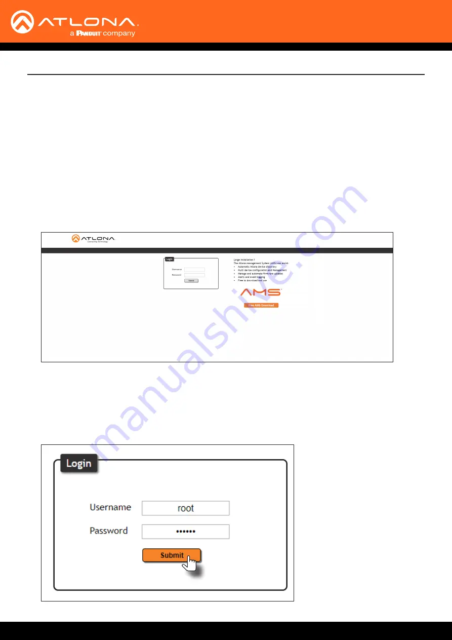
3.  The 

Login

 page will be displayed.

4.  Type 

root

, using lower-case characters, in the 

Username

 field.

5.  Type 

Atlona

 in the 

Password

 field.  This is the default password.  The password field is case-sensitive.  When 

the password is entered, it will be masked.  The password can be changed, if desired.  Refer to the 

Config page 

(page 36)

 for more information.

6. 

Click the 

Submit

 button or press the ENTER key on the keyboard.

The Web GUI

Summary of Contents for ATLONA AT-UHD-CAT-8

Page 1: ...AtlonaManuals DistributionAmplifiers AT UHD CAT 8 HDMI to HDBaseT Distribution Amplifier 4K UHD TM ...

Page 2: ...AT UHD CAT 8 2 Version Release Date Notes 1 Mar 2019 New format 2 Mar 2021 Included instructions for Updating the Valens Firmware page 41 Version Information ...

Page 3: ... to http www atlona com registration Sales Marketing and Customer Support Welcome to Atlona Operating Notes IMPORTANT Visit http www atlona com product AT UHD CAT 8 for the latest firmware updates and User Manual Main Office Atlona Incorporated 70 Daggett Drive San Jose CA 95134 United States Office 1 877 536 3976 US Toll free Office 1 408 962 0515 US International Sales and Customer Service Hours...

Page 4: ...ms New Products 10 years from proof of purchase date for hardware electronics products purchased on or after June 1 2013 3 years from proof of purchase date for hardware electronics products purchased before June 1 2013 Lifetime Limited Product Warranty for all cable products Limited Product Warranty Terms Refurbished B Stock Products and Discontinued Products 3 years from proof of purchase date f...

Page 5: ...ts or states do not allow the exclusion or limitation of relief special incidental consequential or indirect damages or the limitation of liability to specified amounts so the above limitations or exclusions may not apply to you Exclusive Remedy To the maximum extent permitted by law this limited product warranty and the remedies set forth above are exclusive and in lieu of all other warranties re...

Page 6: ...the following two conditions 1 this device may not cause harmful interference and 2 this device must accept any interference received including interference that may cause undesired operation This equipment has been tested and found to comply with the limits for a Class A digital device pursuant to Part 15 of the FCC Rules These limits are designed to provide reasonable protection against harmful ...

Page 7: ...resets 18 Managing Users 19 Adding Users 19 Editing Deleting Users 20 Advanced Operation 21 RS 232 Control 21 Determining the Port Type 21 Cable Assembly 22 Pass through mode 23 Control mode 24 IR Control 25 Controlling Display Devices 25 Controlling Source Devices 26 Power Button Modes 27 Normal Operation 27 Powering Sink Devices 28 Powering Sinks and the AT UHD CAT 8 30 The Web GUI 31 Introducti...

Page 8: ... Ethernet PoE for HDBaseT receivers CEC display control Multi channel audio compliant EDID management Intuitive GUI based configuration using integrated web server TCP IP RS 232 and IR control Easy to configure and manage with AMS Atlona Management System Field updatable firmware Front panel power and signal status LEDs Rack mountable 1U half rack width enclosure Award winning 10 year limited prod...

Page 9: ...t an HDMI cable from this port to a confidence monitor 13 RS 232 IR 1 8 Connect a control system or other DTE device to these ports for pass through zone control Each of these ports uses the associated HDBaseT OUT port This allows RS 232 command data to be sent to a display sink device connected to a PoE comptible receiver 14 HDBaseT OUT 1 8 Connect Ethernet cables from these ports to PoE compatib...

Page 10: ... ports is associated to the respective HDBaseT OUT port This allows RS 232 pass through zone control of a display sink device that is connected to a PoE compatible receiver Control can be performed using RS 232 or electrical IR 1 Connect an HDMI cable from a UHD HD source to the HDMI IN port 2 Connect an HDMI cable from the HDMI OUT port to a display sink device 3 Connect up to eight Ethernet cabl...

Page 11: ...v e n a d d i t i o n a l A T U H D E X 7 0 C T X d e v i c e s E t h e r n e t H D B a s e T LAN Display H D M I H D M I PO WER LIN K FW AT UHD EX 70C RX AT UHD EX 70C RX Laptop AT UHD CAT 8 AT UH D C AT 8 HDM I OUT IN HDB aseT 4 3 2 1 8 7 6 5 POW ER EDID LEAR N INT LOC K ...

Page 12: ...RX LOCK LED indicator IMPORTANT If the AT UHD CAT 8 is receiving a DHCP IP address and the IP mode is changed to static then Telnet and web GUI communication will be lost 1 Make sure the AT UHD CAT 8 is powered 2 Connect an Ethernet cable between the LAN port of the AT UHD CAT 8 and the Local Area Network LAN 3 Press and hold the POWER button for approximately 15 seconds Release the POWER button o...

Page 13: ...address by the DHCP server if present The System page page 37 in the web GUI allows the AT UHD CAT 8 to use either DHCP or static IP mode In order to access the web GUI the IP address of the AT UHD CAT 8 must be known Refer to Introduction to the Web GUI page 31 1 Open the desired web browser and enter the IP address of the AT UHD CAT 8 2 Log in using the required credentials The factory default u...

Page 14: ... HDMI port on the AT UHD CAT 8 and the source display device Try a different HDMI cable HDBaseT 1 8 Blue Normal operation Signal integrity between the AT UHD CAT 8 and the connected receiver is good Off No connection between the HDBaseT port on the AT UHD CAT 8 and the receiver unit Check the Ethernet cable for a secure connection Possible bad cable try a different Ethernet cable LOCK Blue Front p...

Page 15: ...cator will no longer be illuminated Using the Front Panel Using the web GUI 1 Login to the web GUI Refer to Introduction to the Web GUI page 31 for more information 2 Click System in the menu bar 3 Locate the System section and click the Lock toggle button to switch between LOCK and UNLOCK states 4 The LOCK LED indicator on the front panel will reflect the current state When the front panel button...

Page 16: ... powered Learning an EDID using the Front Panel HDBaseT OUT 1 HDMI Display AT UHD CAT 8 AT UHD EX 70C RX PO WE R LIN K FW AT UH D E X 7 0C RX AT UH D C AT 8 HDM I OUT IN HDB aseT 4 3 2 1 8 7 6 5 POW ER EDID LEAR N INT LOC K 4 Press and hold the EDID button on the AT UHD CAT 8 Release the EDID button once the LEARN LED indicator begins to flash rapidly NOTE If the AT UHD CAT 8 is accidentally switc...

Page 17: ...h between LOCK and UNLOCK states 4 Click the EDID mode drop down list and select LEARN 5 Click the COPY button to copy the downstream EDID to memory The AT UHD CAT 8 will now use the EDID of the downstream sink To switch back to the INT mode click the EDID mode drop down list and select INT 4 The LOCK LED indicator on the front panel will reflect the current state When the EDID is locked the LOCK ...

Page 18: ... 720P DD 1 Login to the web GUI Refer to Introduction to the Web GUI page 31 for more information 2 Click EDID in the menu bar 3 Make sure the EDID lock toggle switch is set to UNLOCK 4 Click the EDID mode drop down list and select INT 5 Select the desired EDID from the INT EDID settings drop down list The selected EDID will be used by the source before sending A V data to the display sink device ...

Page 19: ...ry default username and password for the admin user are listed below Username root Password Atlona 3 Click the Config tab 4 Click the Add button under the Edit column 5 Enter the desired username and password in the Username Password Edit dialog box 6 Click the Save Change button to commit changes or click the Cancel button to return to the Config page without adding the user Once created the new ...

Page 20: ... Atlona a Click Config in the menu bar b Click the Edit button next to the user to be changed c Enter the new information for the user in the Username Password Edit dialog box d Click the Save Change button to commit changes or click the Cancel button to return to the Config page without making changes a Click the Remove button next to the user to be deleted The username and password of a user can...

Page 21: ...However this is not always the case If the port type is unknown then a multimeter can be used to determine whether the port is DTE or DCE Determining the Port Type DTE Pin Descriptions DCE Pin Descriptions Pin Signal Description 1 DCD Data Carrier Detect 2 RxD Receive Data 3 TxD Transmit Data 4 DTR Data Terminal Ready 5 GND Ground Signal 6 DSR Data Set Ready 7 RTS Request to Send 8 CTS Clear to Se...

Page 22: ...e 9 Remove at least 3 16 5 mm of insulation from the TxD RxD and GND wires Cable Assembly When connecting a DTE device to a DCE device a straight through cable should be used A straight through cable is wired in such a way that the pins on one side of the cable are connected to the corresponding pins on the opposite side of the cable as shown in the table below However the AT UHD CAT 8 will use on...

Page 23: ...o the desired RS 232 IR port on the AT UHD CAT 8 Refer to Cable Assembly page 22 for instructions on preparing the cable 2 Connect an Ethernet cable from the desired HDBaseT OUT port to a receiver In this example the HDBaseT cable is connected from HDBaseT OUT 2 to an AT UHD EX 70C RX receiver the RS 232 cable is connected from the control system to the RS 232 IR 2 port 3 Connect an RS 232 cable b...

Page 24: ...M NC NO 12V SIG GND 12V SIG GND 12V SIG GND 12V SIG GND 1 COM PON ENT HDM I 1 2 3 4 5 6 SERI AL 1 IR OUT SERI AL 2 L R DIGIT AL COA X OUT AUD IO OUT AUD IO IN ETHE RNE T 2 3 4 VIDE O OUT 48V DC FAC TORY RESE T Control System AT UHD CAT 8 AT UH D C AT 8 HD MI OU T IN HD Bas eT 4 3 2 1 8 7 6 5 POW ER EDI D LEA RN INT LOC K 3 Click RS 232 in the menu bar 4 Select the proper baud rate data bit parity ...

Page 25: ...ng Display Devices IR RS 232 IR 1 HDBaseT HDBaseT OUT 1 IR Emitter 2 COM NC NO COM NC NO COM NC NO COM NC NO 12V SIG GND 12V SIG GND 12V SIG GND 12V SIG GND 1 COMP ONEN T HDMI 1 2 3 4 5 6 SERIA L 1 IR OUT SERIA L 2 L R DIGIT AL COAX OUT AUDIO OUT AUDIO IN ETHE RNET 2 3 4 VIDEO OUT 48V DC FACT ORY RESET AT UHD EX 70C RX Display Control System IR Signal POW ER LINK FW AT U HD EX 7 0C R X AT UHD CAT ...

Page 26: ...ontrolled 5 Place the IR emitter next to the source device R X G N D Controlling Source Devices IR Emitter RS 232 IR 1 HDBaseT HDBaseT OUT 1 IR Receiver Blu ray Player IR Remote Blu ray Player IR Signal PO WE R LIN K FW AT UH D E X 7 0C RX AT UHD EX 70C RX AT UHD CAT 8 AT UHD CA T 8 HD MI OU T IN HD Bas eT 4 3 2 1 8 7 6 5 PO WE R EDI D LEA RN INT LOC K Advanced Operation HDMI OUT IN HDBaseT 4 3 2 ...

Page 27: ...WER button will be blue Pressing the POWER button again will place the unit into standby mode and the POWER button will be red In standby mode no video signal will pass to the display sink device However TCP IP access to the unit will be maintained allowing access to the web GUI and Telnet sessions 1 Launch a web browser and login to the web GUI Refer to Introduction to the Web GUI page 31 for mor...

Page 28: ... 31 for more information The factory default username and password are listed below Username root Password Atlona 4 Click System in the menu bar 5 Click the Power button mode drop down list and select CEC Refer to the illustration on the next page for reference Consumer Electronics Control CEC Atlona has confirmed proper CEC functionality with several current models of Samsung Panasonic and Sony d...

Page 29: ...e CEC power on and power off commands by pressing the ON and OFF buttons near the bottom of the page 7 Press the POWER button on the front panel to power on or power off the display Note that the power state of the AT UHD CAT 8 will be unaffected ...

Page 30: ...the POWER button on the front panel to power on or power off both the display and AT UHD CAT 8 Consumer Electronics Control CEC Atlona has confirmed proper CEC functionality with several current models of Samsung Panasonic and Sony displays However it is not guaranteed that CEC will work with all displays Many manufacturers do not support the CEC off command and older displays use proprietary comm...

Page 31: ...efer to IP Configuration page 12 The default static IP address of the AT UHD CAT 8 is 192 168 1 254 Introduction to the Web GUI 1 Launch a web browser 2 In the address bar type the IP address of the AT UHD CAT 8 3 The Login page will be displayed 4 Type root using lower case characters in the Username field 5 Type Atlona in the Password field This is the default password The password field is case...

Page 32: ...olored bar near the top of the screen is the menu bar When the mouse is moved over each menu element it will be highlighted in light orange Once the desired menu element is highlighted click the left mouse button to access the settings within the menu In this example moving the mouse over the RS 232 menu item will highlight it Click the RS 232 menu item to display the RS 232 page Menu bar ...

Page 33: ...sion of firmware that the AT UHD CAT 8 is running Always make sure to check the AT UHD CAT 8 product page on the Atlona web site for the latest version of firmware Output 1 VALENS Version Output 8 VALENS Version The version of firmware on the HDBaseT chip for each HDBaseT OUT port The Web GUI ...

Page 34: ...0 38400 56000 57600 115200 Data bit Sets the number of data bits used to represent each character of data The following options are available 7 or 8 Parity Sets the parity bit which can be included with each character to detect errors during the transmission of data The following options are available None Odd or Even Stop bit Sets the stop bit Stop bits are sent at the end of each character allow...

Page 35: ...CH ATL 3840x2160 30 2CH ATL 1080P 3D Multi CH ATL 3840x2160 30 Multi CH ATL 1080P 3D DD ATL 3840x2160 60 2CH ATL 720P 2CH ATL 3840x2160 60 Multi CH ATL 720P DD EDID mode Description INT Internal mode Uses the default internal EDID LEARN Learn mode Reads the EDID of the sink device connected to the HDBaseT OUT 1 port Once the EDID is learned it will be used by the connected source device to determi...

Page 36: ... Password Enter the new password for the root username in this field Confirm New Password Verify the new password by retyping it in this field All User Login Settings Username Displays the username Password Displays the password for the associated username Edit Click the Add button in this column to edit the username and password in the row Del Click the Remove button to delete the user in the row...

Page 37: ...e Click this toggle to set the login mode to either ON or OFF If this feature is set to ON then the AT UHD CAT 8 will prompt for both the username and password at the start of a Telnet session Use the same credentials as the web GUI Telnet Timeout Click this drop down list to select the timeout interval in seconds before the Telnet connection is automatically closed after no activity Range 1 to 36...

Page 38: ... the CEC protocol Power on and power off commands are sent over both the HDBaseT OUT and HDMI OUT ports Reset to Default Click the Factory Default button to set the AT UHD CAT 8 to factory default settings Firmware Update Click the Choose File button to select the firmware file when upgrading the firmware on the AT UHD CAT 8 Once the firmware file is selected click the Update button Refer to Updat...

Page 39: ...le from the computer containing the firmware to the same network where the AT UHD CAT 8 is connected 2 Go to the System page page 37 in the web GUI Choose File button Appendix 3 Click the Choose File button under Firmware Update 4 Browse to the location of the firmware file select it and click the Open button 5 Click the Update button to begin the update process 6 The following message box will be...

Page 40: ...B A to USB mini B cable between the PC and the firmware port on the AT UHD CAT 8 5 The USB UPDATE folder will be displayed If this folder is not displayed automatically select the USB UPDATE drive from Windows Explorer Appendix Using USB 7 Delete all files from the USB UPDATE drive if any are present 8 Drag and drop the firmware file to the drive During the firmware update procedure the POWER butt...

Page 41: ... an Ethernet cable from the computer containing the firmware to the same network where the AT UHD CAT 8 is connected 2 Go to the System page page 37 in the web GUI Choose File button 3 Click the Choose File button under Valens Update 4 Browse to the location of the firmware file select it and click the Open button 5 Click the Update button to begin the update process 6 The following message box wi...

Page 42: ...t the USB A to USB mini B cable between the PC and the firmware port on the AT UHD CAT 8 5 The USB UPDATE folder will be displayed If this folder is not displayed automatically select the USB UPDATE drive from Windows Explorer Using USB 7 Delete all files from the USB UPDATE drive if any are present 8 Drag and drop the firmware file to the drive During the firmware update procedure the POWER butto...

Page 43: ... CAT6a CAT7 Solid Unshielded Twisted Pair UTP N A N A Shielded Twisted Pair STP Refer to the tables below for recommended cabling when using Altona products with HDBaseT The green bars indicate the signal quality when using each type of cable Higher quality signals are represented by more bars EIA TIA 568 B Termination IMPORTANT Stranded or patch cables are not recommended due to performance issue...

Page 44: ... Parity Stop bit 115200 8 None 1 EDID EDID lock EDID mode INT EDID settings UNLOCK INT STD Config Username default Password default root Atlona System IP Mode Static IP Address default Netmask Gateway Telnet Port Telnet Login Mode Telnet Timeout Broadcast Power Lock Power button mode DHCP 192 168 1 254 255 255 0 0 192 168 1 1 23 OFF 120 ON ON UNLOCK DA standby ...

Page 45: ...Dolby TrueHD Dolby Atmos DTS DTS HD Master Audio DTS X Sample Rate 32 kHz 44 1 kHz 48 kHz 88 2 kHz 96 kHz 176 4 kHz 192 kHz Bit Depth Up to 24 bit Protocols Addressing DHCP static Management HTTP Telnet Indicators and Controls Control Buttons POWER EDID 2 momentary tact type LED Indicators HDMI IN OUT HDBaseT 1 8 LOCK INT LEARN 9 LED blue Control CEC Display control RS 232 Device control and confi...

Page 46: ...olution Distance 4K UHD Feet Meters 1080p Feet Meters HDMI IN OUT 15 5 30 10 CAT5e 115 35 200 60 CAT6 6a 7 130 40 230 70 Power Consumption 85 70 W Idle Consumption 18 40 W External Power Supply Input 100 240 V AC 50 60 Hz Output 48 V DC 2 08 A Safety CE FCC Level IV cULus RoHS RCM CCC Environmental Operating Temperature 32 to 122 F 0 to 50 C Storage Temperature 4 to 140 F 20 to 60 C Operating Humi...

Page 47: ...Toll free US International atlona com 877 536 3976 41 43 508 4321 35231 R4 ...

Reviews: