


AT-OME-ST31A
31
Configuration and Management Interfaces
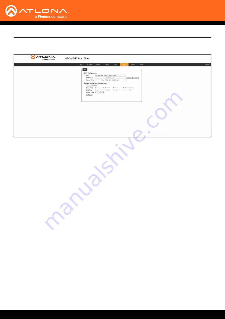
SNTP Configuration
Simple Network Time Protocol (SNTP) is a simplified version of the Network Time Protocol (NTP), and can be used
to set the time for the unit. SNTP is used to receive time services from other servers. However, it cannot be used to
provide time servers to other systems.
•
GMT
Click this drop-down list to select the Greenwich Mean Time (GMT) for the current location.
• NTP Server
Enter the desired NTP server address in this field. After entering the NTP server address, click the
Sync
button.
• Sync button
Click this button to sync with the server, after entering the desired NTP server address.
• Save button
Click this button to commit changes to the NTP Server field. If a save is not performed, then the NTP server
address will not be saved.
• Server Time
This field will display the current time.
Daylight Saving Time Configuration
Click the toggle switch button to
ENABLE
or
DISABLE
Daylight Saving Time (DST). This feature is disabled by
default.
• Start Time
Click each of these drop-down lists to select the month, week, day, and time (HH:MM) when DST begins.
• End Time
Click each of these drop-down lists to select the month, week, day, and time (HH:MM) when DST ends.
• Adjust Time
Click these drop-down lists to set the hour and minute to adjust the clock for DST.
• Save
Click this button to commit all changes.
Time Page