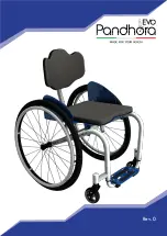
background image

1

User Guide

Rev. 0

Summary of Contents for Evo

Page 1: ...1 User Guide Rev 0...

Page 2: ...2...

Page 3: ...2 Start using the wheelchair Determining tipping point 2 3 Negotiating Objects 2 4 Pavements 2 5 Ascent and Descent stairs and steps 2 6 Narrow Openings 2 7 Use in Lifts 2 8 Tire Pressure 2 9 Quick Re...

Page 4: ...e brakes 5 7 Pelvic Belt 5 8 Push handles 5 9 Multi Seating 5 10 Sandy add on Wheel 6 Settings 6 1 Backrest Height adjustment 6 2 Backrest Angle adjustment 6 3 Wheel Guard Width adjustment 6 4 Footres...

Page 5: ...5 7 Maintenance Declaration of Conformity WARRANTY PLATE AND CE MARKING WARRANTY COUPON 64 66 68 70 71...

Page 6: ...ly commitment of our team We carefully study new solutions to offer innovative and techni cally advanced products with the goals of practical and elegant design high comfort and reliability We believe...

Page 7: ...absolutely General information to improve usage Essential tool You need to have a spanner for 5mm nuts or bolts Essential tool You need to have a spanner for 6mm nuts or bolts Essential tool You need...

Page 8: ...signed to have elegance when in motion A wide range of accessories allows you to customize the Pandho ra EVO to make it personal to you The bearing structure was designed to be robust and elegant and...

Page 9: ...essories and configurations In the case of users with a serious reduction in physical ability it is always recommen ded to use the wheelchair with the presence of a carer The EVO is not recommended fo...

Page 10: ...e original manu facturer Altering the design of the wheelchair may create stability and resistance problems resulting in danger for the user FAILURE TO FOLLOW ALL INSTRUCTIONS IN THIS USE AND MAINTENA...

Page 11: ...carer if required Only work within your capability and degree of autonomy General guidance for safe and secure transfers Place the wheelchair on a flat dry solid surface Avoid tran sferring on sloping...

Page 12: ...12 Pic 1...

Page 13: ...13 When transferring into or out of the wheelchair do not push down on or sit on the wheel sideguards They could bend or break with the risk of injury Pic 2 Pic 3...

Page 14: ...ehind the wheelchair to prevent it from tipping completely To determine the tipping point and therefore understand the safe limits of your maneuvers proceed as follows see pic 4 You are sitting in you...

Page 15: ...15 TO PREVENT TIPPING OVER DURING THE NORMAL USE OF THE WHEELCHAIR IT IS RECOMMENDED TO INSTALL THE AN TI TIPPING SYSTEM SUPPLIED AS AN ACCESSORY ON THIS MODEL see chapter 6 6 Pic 4...

Page 16: ...balance of the wheelchair especially if the wheelchair has been configured with a reduced width or if the seated position is high see pic 5 The risks include Overturning in case of reaching forward L...

Page 17: ...2 4 Pavements Pic 7 Pic 8 Be careful before you manoeuvre down a kerb by yourself you need to properly evaluate the height of the kerb If it is too high there is a risk of tipping over see fig 7 fig...

Page 18: ...heelchair must be rolled on the big rear wheels and accompa nied step by step For the ascent turning your back to the step or steps the person assisting must pull the wheelchair from behind step by st...

Page 19: ...re the correct braking and coasting characteristics of the wheelchair it is necessary that the tires are always well inflated Remove the plastic cap cove ring the valve with your fingers see pic 9 Use...

Page 20: ...nsert fingers between the spokes Push and pull the wheel as indicated by the arrow for proper insertion Anti Puncture Marathon Plus 10 BAR 1000 kPA High Pressure 7 BAR 700 kPA High pressure reinforced...

Page 21: ...threading of the studs from the rear wheel causing the subsequent overturning of the wheelchair and possible injury to the user see pic 10 Checking the rear wheels studs is one of the proce dures that...

Page 22: ...elchair and if necessary re quest the assistance of authorized Pandhora approved personnel for maintenance of the wheelchair 2 11 Expected lifetime of the wheelchair Expecting that the wheelchair will...

Page 23: ...areful when using braking devices to avoid injury to hands and fingers 2 12 Prevent accidents When using the wheelchair avoid high stress movements because this could cause the wheelchair to overturn...

Page 24: ...car or another means of transport Disassemble the wheelchair as spe cified in the instructions for use and put it inside the car or place it in such a way as to avoid accidents in case of sudden movem...

Page 25: ...ers If transporting the wheelchair appears to be risky or complicated it is appropriate to request the help of a companion 3 1 Transport with the presence of a companion If the user s disability or ph...

Page 26: ...t see paragraph 5 2 Closing the Backrest Take the wheelchair with one hand on the front frame and with the other on the rear frame to make lifting less strenuous Lift the wheelchair into the car ideal...

Page 27: ...ver s seat Brake the wheelchair with brakes and transfer into the vehicle Release the parking brake of the wheelchair and remove the rear wheels Lower the backrest take the wheelchair with one hand on...

Page 28: ...28 4 Separate Parts Description 1 2 3 4 5 6 7 8 9 10 11 12 13 Pic 15...

Page 29: ...guards 2 Adjustable backrest 3 Seating 4 Wheelchair frame 5 Parking Brakes 6 Pushing handles 7 Anti tip 8 Rear wheel tire 9 Ring handrails 10 Quick release pin 11 Front fork 12 Front wheel 13 Adjusta...

Page 30: ...ted for daily use by active users and by users with serious illnesses for indoor and outdoor use see pic 15 Do not adjust the wheelchair when situated on uneven ground Once adjusted use caution and av...

Page 31: ...between the back tube and the side guards during the closure of the backrest it is better to grip the push handles see pic 16 Remove the pillow or soft supports on the seat Push the lever under the r...

Page 32: ...32 Press the back button and push the backrest forward see pic 17 18 and 19 Pic 17 Pic 18...

Page 33: ...not go between the back tube and the side guards Push the lever under the tubular frame from the inner side Rotate the backrest backward to the desired posi tion Place the pillow or soft supports on t...

Page 34: ...34 Press the front button and push the backrest back see pic 20 and 21 Pic 20 Pic 21...

Page 35: ...35 To lock it in the open position press the rear button see pic 22 and 23 Pic 22 Pic 23...

Page 36: ...balance during the lifting see Chapter 5 2 Closing the Backrest Grasp the wheelchair on the back of the seat with one hand and the front frame with the other hand Lift the wheelchair 5 5 Fast rear whe...

Page 37: ...ut ton with your thumb and without releasing insert the PIN into the end in the axle slot Release the pin button to lock the wheel Make sure that the quick draw pins are fully se ated Always test by g...

Page 38: ...ng the brakes Lock the brakes Push the lever forward if push to lock brakes are used Pull the le ver backwards if pull to lock brakes or scissor brakes have been mounted See pic 25 26 27 28 1 2 3 4 Pi...

Page 39: ...0 31 32 1 2 3 4 Pressure Brakes work by applying leverage directly onto the tires For this reason the effectiveness of the brake depends on its correct positioning and the cor rect air pressure in the...

Page 40: ...s with little control of the torso The user is bound to the backrest at the waistline level leaving the upper torso free to move The pelvic belt is firmly anchored to the backrest The use is quite eas...

Page 41: ...cal bands which are practically indestructible In this way the weight of the wheelchair is further reduced and also have zero footprint It should be noted that these innovative push handles avoid comm...

Page 42: ...the backrest in the desired position see pic 35 36 37 38 In this way the backrest can also be rotated backward and up towards the front to be used as a leg rest In the case of active users this can b...

Page 43: ...43 Pic 35 Pic 36 Pic 37 Pic 38 Pic 39 Pic 40...

Page 44: ...cellent for towing can be used for driving if matched to rear beach wheels The installation of the front wheel takes place in a few simple steps Thanks to its shape the sea wheel remains firmly on the...

Page 45: ...45 Pic 42 Pic 43 Pic 44...

Page 46: ...is person Allowing another person to use the wheelchair might cause the wheelchair to become unstable with unpredicatble consequences that could lead to the wheelchair tipping over with serious conseq...

Page 47: ...damage to both the wheelchair and its user At the end of each adjustment made to the whe elchair scrupulously check that all parts are well fixed check the closing of screws and bolts and the smooth...

Page 48: ...are as follows Using an allen wrench hex key and an M6 nut wren ch remove the bolts with their saddle nuts and washers Place the backrest at the preferred height Re insert the bolts into the hole at...

Page 49: ...with continuous adjustment from 0 to 300 patented and adjustable with a simple click Press the lever in the direction you want to move the backrest The same process should also be used when you want t...

Page 50: ...o your needs The guard sides are equipped with loops to translate their position inward or outward Using an allen wrench hex key and an M5 nut wren ch loosen the bolts Place the side guards at the pre...

Page 51: ...holes that coupled with the hole in the frame of the wheelchair allow height adjustment of the footrest Remove the two bolts A with an allen key for M5 bolts and two M5 nuts with a wrench Slide the fo...

Page 52: ...rk type used see pic 49 To adjust the height Remove the bolts with a 4mm allen wrench Locate the wheel into the holes present on fork ac cording to the desired height Insert the bolts and tighten firm...

Page 53: ...a distance of 2 3 cm from the ground The anti tip wheel can be removed entirely if there is a need To remove the anti tip wheel press with your thumb on the spring plug tip and pull the anti tip post...

Page 54: ...54 Use your thumb to press on spring plug tip and pull the anti tip post out see pic 52 3 4 Pic 52 Pic 53...

Page 55: ...tate the anti tip post inwards into the desired posi tion Note that this is simply to move the anti tip out of the way tempo rarily The anti tip will not function unless the spring plug is locked into...

Page 56: ...nd more reactive for more active users Moving the location of the seat further away from the CoG makes the chairs less easy to tilt and suitable for users who need more sta bility and security see pic...

Page 57: ...57 Pic 57 Pic 58...

Page 58: ...careful when adjusting the damping cushioning The seat must not have a reduction greater than 15mm Adjustable only by qualified personnel Using an allen wrench for M6 bolts hex key and M6 nut driver...

Page 59: ...59 Pic 59...

Page 60: ...e that sup ports the back Using an allen wrench hex key for M5 bolts and M5 nut driver remove the nuts and bolts Move the plate to the desired position aligning the holes in the plate that holds the b...

Page 61: ...orrect brake function by completing braking tests Check for proper locking of the mechanism attachments by moving the brake lever energetically If the brake support should move or slip during such tes...

Page 62: ...e brakes Using an allen wrench hex key for M6 bolts loosen bolts A and B on the brake support Then position the brake in order to find the right set ting Fasten bolts A and B see pic 61 Follow the sam...

Page 63: ...63...

Page 64: ...the date of purchase of the whe elchair Failing to do so can immediately void the warranty and relieve the company from any liabi lity arising from possible faults or breakages Maintenance must be car...

Page 65: ...ation number The VIN vehicle identification number is located on the CE sticker marking a silver sticker placed on the tube of the central frame For safety reasons only use spare par ts and accessorie...

Page 66: ...phone fax 39 089 825929 mobile 39 328 95 32 556 E mail info pandhora it website www pandhora it VAT nr 02726920420 registration number 02726920420 Chamber of Commerce VAT nr 02726920420 REA 210485 wit...

Page 67: ...nd transposition of 25 January 2010 the Italian Decree Law 37 of that directive The product above is classed as NON invasive class I medical de vices as specified in annex IX and X to Directive CEE 20...

Page 68: ...e spare parts and accesso ries authorized by Pandhora The use of spare parts and acces sories not approved by Pandhora S r l are reason for immediate forfeiture of the guarantee In order to ensure the...

Page 69: ...ts of aid resulting in dy sfunction for operating or manufacturing faults provided that they are communicated directly to freight forwarder upon delivery 3 for safety reasons use authorized spare part...

Page 70: ...s them necessary The Pandhora S r l declines all responsibilithings animals and third parties due to changes or misuse of the wheelchair PLATE AND CE MARKING The CE label see picture on the wheelchair...

Page 71: ...user _____________________________________ Address ____________________________________________ Locality ___________________________State _____________ ZIP Code _____________Phone_____________________...

Page 72: ...18 1 2 19 19 1 419 3 4 20 20 1 4 depends on SD BRH KHL 32 34 36 38 40 12 1 213 1 414 1 4 15 15 3 4 depends on SHF 32 34 36 38 40 12 1 213 1 414 1 4 15 15 3 4 Some measures may not be available as they...

Reviews: