background image

10

Step 2

Mount the cable cap (accessory) on the cable access hole 
(front).

Step 3

Make a slit in the center of another cable cap (accessory) 
with a cutter.

Cable cap 
(accessory)

Step 4

Remove the 4 screws from the rear side of the bracket, 
remove the plate, and mount the cable cap that was slit in 
Step 3.

Step 1

Decide the mounting position, and drill holes for screws or 
anchors and a hole for cable installation in the ceiling.
Procure 4 pieces of M10 screws and anchors to secure the 
this bracket on the ceiling.
For screws and anchors to be used, make sure that enough 
salt damage prevention is applied. The hole diameter shall 
be decided in accordance with the screws and anchors to 
be used.
A hole on the ceiling with a diameter of 30 mm {ø 1-3/16 
inches} or less for a screw or an anchor can be hidden with 
this bracket.

* The above measurement diagram shows the view when 

standing on the floor and looking up at the ceiling.

 When laying cables after drilling a hole through the ceiling

80 mm
{3-5/32 inches}

120 mm

{4-3/4 inches}

180 mm

{7-3/32

 inches}

Hole for cable 

installation: ø38 mm 

{ø1-1/2 inches}

Summary of Contents for WV-Q121BS

Page 1: ...ual for future use The model number is abbreviated in some descriptions in this manual Operating Instructions Included Installation Instructions Ceiling Mount Bracket Model No WV Q121BS Heavy salt damage prevention applied The camera in the illustration is separately sold avs0516 2109 PGQX2047XA Printed in China ...

Page 2: ...2 Preface 3 Precautions 3 Precautions for installation 4 Major operating controls 5 Installations Connections 6 Specifications 14 Standard accessories 14 CONTENTS ...

Page 3: ...tallation surface may cause this product to fall down or topple over resulting in injury or accidents Installation work shall be started after sufficient reinforce ment Do not rub the edges of metal parts with your hand Strong rubbing may cause injury Periodic inspections shall be conducted Rust on the metal parts or screws may cause a fall of the product resulting in injury or accidents Consult t...

Page 4: ... to be used as a pendant mount camera If the product is mounted on a desktop or at a slant it may not work correctly and its lifetime may be shortened Protection from lightning When cables are used outdoors there is a chance that they may be affected by lightning In this case install a lightning arrester close to the camera to prevent it from being affected by lightning and keep the length of the ...

Page 5: ...rols Hexagonal screw hole for mounting camera 4 points Wire hook section Camera mounting part Cable access hole front Plate Cable access hole rear 220 mm 8 21 32 inches 269 mm 10 19 32 inches 1 2 0 m m 4 2 3 3 2 i n c h e s ...

Page 6: ... attaching the camera to the ceiling mount bracket detach the housing base and attachment pipe from the camera so that installation and connections can be performed Step 1 Remove the fixing screws 3 pcs that are securing the housing base and the camera The removed screws will be required when attaching the camera to the housing base Use caution not to lose these screws Special screw fixing screw T...

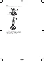
Page 7: ...chment pipe from the housing base by loosening 4 screws Go to When laying cables through the cable access hole front 8 page or When laying cables after drill ing a hole through the ceiling 10 page Attachment pipe Housing base ...

Page 8: ...hole front Step 1 Decide the mounting position and drill a hole through the ceiling Procure 4 pieces of M10 screws and anchors to secure the this bracket on the ceiling For screws and anchors to be used make sure that enough salt damage prevention is applied The hole diameter shall be decided in accordance with the screws and anchors to be used A hole through the ceiling with a diameter of 30 mm ø...

Page 9: ...with 4 screws M10 locally procured Minimum pull out strength 1411 N 317 lbf per 1 pc Step 7 Connect the cables to the camera outside the cable access hole front of the WV Q121B Connect the cables from the housing base with the cables on the ceiling After cable connection seal the connecting portion with waterproof tape locally procured IMPORTANT These operations shall be performed in accordance wi...

Page 10: ...0 screws and anchors to secure the this bracket on the ceiling For screws and anchors to be used make sure that enough salt damage prevention is applied The hole diameter shall be decided in accordance with the screws and anchors to be used A hole on the ceiling with a diameter of 30 mm ø 1 3 16 inches or less for a screw or an anchor can be hidden with this bracket The above measurement diagram s...

Page 11: ...ate with the 4 screws removed in Step 4 on the rear side of the bracket and seal the slit of the cable cap Recommended tightening torque 0 78 N m 0 58 lbf ft Step 6 Connect the cables above the ceiling Connect the cables from the housing base with the cables coming through the ceiling After cable connection seal the connecting portion with waterproof tape locally procured IMPORTANT These operation...

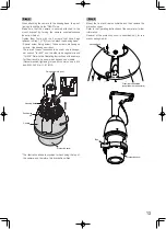
Page 12: ...m Communication method specifying with SW2 Unit address specifying with SW1 RS485Setting START S W 1 SW2 D I P S W 1 O N 1 2 3 4 5 6 7 8 DIP SW 2 ON 1 2 3 4 DIP switch Seal Camera top Step 2 Align the flat spring with the START position If not rotate the plate on the top of the camera clockwise to align it with the START position For the case of network camera For the case of color CCTV camera Ste...

Page 13: ...is hexagonal wrench for M6 Refer to the Operating Instructions of the camera for the wrench to be used which depends on models Recommended tightening torque for common use in M5 and M6 2 45 N m 1 81 lbf ft The illustration above is provided for describing the top of the camera and therefore this bracket is omitted Fixing screws 3 pcs Housing base Positioning pin Camera Protection cover Step 5 Moun...

Page 14: ...cast Heavy salt damage prevention coating Silver metallic Others Heavy salt damage prevention ISO14993 compliant Weight and dimensions indicated are approximate Specifications are subject to change without notice Specifications Operating Instructions this document 1 set The following are for installation Cable cap 2 pcs Camera mounting screw Hexagon screw M6 5 pcs of them 1 for spare Standard acce...

Page 15: ...15 ...

Page 16: ... Drive Mississauga Ontario L4W 2T3 Canada 1 877 495 0580 https www panasonic com ca Panasonic i PRO Sensing Solutions Co Ltd 2019 For Europe and other countries Panasonic Corporation http www panasonic com Panasonic i PRO Sensing Solutions Co Ltd Fukuoka Japan Authorised Representative in EU Panasonic Testing Centre Panasonic Marketing Europe GmbH Winsbergring 15 22525 Hamburg Germany ...

Reviews: