

(To be continued reverse page)
1. Camera Identification (CAMERA ID) Setting
You can use the camera identification (CAMERA ID) to assign a name to the camera. The camera
ID consists of up to 16 alphanumeric characters. The camera ID display can be switched on or off
on the monitor screen.
To edit the CAMERA ID
1. Move the cursor to CAMERA ID.
The factory default setting is OFF.
2. Press
I
(S). The CAMERA ID menu appears.
The cursor on the letter “0” is highlighted.
3. Move the cursor to the character you want to edit
by pressing
I
(L) /
I
(R) /
I
(U) /
I
(D).
4. After selecting the character, press
I
(S). The
selected character appears in the editing area.
(The pointer in the editing area moves to the right
automatically at this moment.)
5. Repeat the steps above until all characters are
edited.
To enter a blank space in the CAMERA ID
Move the cursor to SPACE and press
I
(S).
To replace a specific character in the CAMERA ID
1. Move the cursor to the editing area by pressing
I
(D).
2. Move the pointer to the character to be replaced by pressing
I
(L) or
I
(R). Then move the
cursor to the character area and select a new character.
3. Press
I
(S) to determine the CAMERA ID.
To erase all characters in the editing area
Move the cursor to RESET and press
I
(S). All characters in the editing area disappear.
To determine the display position of the CAMERA ID
1. Move the cursor to POSI, and press
I
(S). The display at right appears and the CAMERA ID
is highlighted.
2. Move the CAMERA ID to the desired position by
pressing
I
(L) /
I
(R) /
I
(U) /
I
(D).
3. Press
I
(S) to fix the position of the CAMERA
ID. The mode returns to the previous CAMERA ID
menu.
Notes:
• The CAMERA ID stops at the edges of the
monitor screen.
• The CAMERA ID moves faster if any of
I
(L) /
I
(R) /
I
(U) /
I
(D) is kept pressed
for a second or more.
2. Light Control Setting (ALC)
2-1. ALC Mode with SUPER-D2 ON
Super Dynamic2 Function (SUPER-D2)
The important object in a scene is usually placed in the center of the monitor screen. In the SUPER-
D2 mode, more photometric weight is given to the center of the screen (where the important object
is located) than to the edge of the screen (where a bright backlight would most likely be located).
The SUPER-D2 function eliminates interference by strong background lighting which makes the
camera picture dark, such as a spotlight.
1. Move the cursor to ALC and press
I
(S). The ALC CONT menu appears.
2. Move the cursor to SUPER-D2 and select ON.
3. If you want to adjust the video output level,
move the "I" cursor for LEVEL. Adjust to the
desired level by pressing
I
(L) or
I
(R).
SETTING PROCEDURES
** ALC CONT **
BACK LIGHT COMP
SUPER-D2 ON
LEVEL ...I.....
- +
RET END
WV-CW374
Highlighted
0123456789
ABCDEFGHIJKLM
NOPQRSTUVWXYZ
().,'":;&#!?=
+-*/%$
SPACE
POSI RET END RESET
................
Character Cursor
Pointer
Character
Area
Command
Editing
Area
CAMERA ID menu
Caution: For camera
Connect to 12 V DC (10.5-16 V) or 24 V AC 60 Hz (19.5 V-28 V) class 2 power supply only.
Make sure to connect the grounding lead to the GND terminal when the power is supplied
from a 24 V AC 60 Hz power source.
!4
!3
!3
Power cable (for camera/heater)
1. CAMERA SETUP MENU
This camera utilizes an on-screen user setup menu.
• Opening the Setup Menu
Press and hold down
I
(S) for 2 seconds or
more.
The CAM SET UP menu appears on the monitor as
shown at right.
Check the current settings on the menu.
Refer to the following sections for a detailed description of menu items. If you decide not to make
any changes after checking the current settings, move the cursor to END in the bottom line, and
press
I
(S) to close the setup menu.
Note:
If no button is pressed for 5 minutes while a setup menu is being displayed on the monitor
screen, it is automatically closed and the mode returns to the normal camera picture.
2. SETUP OPERATION
This camera utilizes an on-screen user setup menu (CAM SET UP). To set items on the CAM SET
UP menu, use the following buttons on the back.
Left Button
(
I
) (L)
:
Moves the cursor to the left. Use this button to select or adjust the para-
meters of the selected item. The parameter changes each time this button
is pressed.
Right Button
(
I
) (R)
: Moves the cursor to the right. Use this button to select or adjust the para-
meters of the selected item. The parameter changes each time this button
is pressed.
Up Button
(
I
) (U)
:
Moves the cursor upwards. Use this button to select an item or adjust the
parameters.
Down Button
(
I
) (D)
: Moves the cursor downwards. Use this button to select an item or adjust
the parameters.
Set Button
(
I
) (S)
:
Executes selections and displays a submenu for an item with the
mark.
• To reset the parameter to the factory default setting, move the cursor to the parameter to be
reset and press
I
(L) and
I
(R) simultaneously.
• To return to the previous menu or page, move the cursor to RET and press
I
(S).
• To close the setup menu, move the cursor to END and press
I
(S).
• All Reset Operation
All Reset allows you to reset all setup menu items to the factory default settings if you are unsure
about the correct settings. Proceed as follows:
(1) Make sure that the CAM SET UP menu is not displayed (a camera picture is displayed).
(2) While pressing both
I
(L) and
I
(R), press
I
(S) for a few seconds. The message ALL
RESET momentarily appears on the monitor screen.
This resets all adjustments and parameters to the factory default settings except for the PIX
OFF setting.
• Editing the CAM SET UP Menu
Important Notice:
When SET UP DISABLE appears in the bottom line of the CAM SET UP menu, you cannot
change the currently active settings. This is to prevent accidental changing of the settings.
To edit the CAM SET UP menu (change settings), press
I
(U) and
I
(D) or
I
(L) and
I
(R) to
move the cursor to SET UP DISABLE in the bot-
tom line.
Press
I
(S). SETUP DISABLE changes to
SETUP ENABLE. Move the cursor to DIP SW.
Press
I
(S). DIP SW changes to MENU. Then
move the cursor to the item(s) you want to
change.
Notes:
• When DIP SW is selected for CAM SET UP menu, six modes can be set with the DIP switches.
• To operate the camera functions with the system controller, select MENU in the CAM SET UP
menu.
Important Notice:
When the setup menu is closed after changing the parameters in the menu, the new values are
stored in the EEPROM (Electrically Erasable and Programmable Read-Only Memory). These
values remain valid until new values are stored, even if the power of the camera is off.
↵
** CAM SET UP **
CAMERA ID OFF
ALC ALC
SHUTTER ---
AGC ON(HIGH)
SENS UP OFF
SYNC INT
WHITE BAL ATW1
MOTION DET OFF
LED ON
DIP SW
END SET UP DISABLE
↵
↵
↵
** CAM SET UP **
CAMERA ID OFF
ALC ALC
SHUTTER ---
AGC ON(HIGH)
SENS UP OFF
SYNC INT
WHITE BAL ATW1
MOTION DET OFF
LED ON
MENU
END SET UP ENABLE
↵
↵
↵
↵
↵
SETUP
↵
↵
↵
↵
** CAM SET UP **
CAMERA ID OFF
ALC ALC
SHUTTER ---
AGC ON(HIGH)
SENS UP OFF
SYNC INT
WHITE BAL ATW1
MOTION DET OFF
LED ON
DIP SW
END SET UP DISABLE
1. The following functions are built in.
(1) Auto Light Control (ALC)
(2) The SUPER-D
2
function eliminates interference by strong background lighting which
makes the camera picture dark, such as a spotlight.
Dynamic range of 46 dB (Typical)
(3) Internal, Line-Locked, Multiplexed Vertical Drive (VD2) Sync
(4) Auto/Manual White Balance Function
(5) Electronic Shutter Function
2. Signal-to-noise ratio of 50 dB (Equivalent to AGC Off)
3. Minimum illumination of 1.0 lx (0.10 footcandle) (WIDE) (Color mode)
Minimum illumination of 0.15 lx (0.015 footcandle) (WIDE) (Black-and-white mode)
4. 480 lines of horizontal resolution (Color normal mode)
510 lines of horizontal resolution (Color High Resolution mode)
570 lines of horizontal resolution (Black-and-white mode)
5. High quality picture:
(a) 2H type vertical enhancer for greater picture sharpness
(b) Chroma averaging circuit for better color signal-to-noise ratio
(c) Minimum of aliasing on fine objects
(d) Expanded dynamic range by use of knee circuit
(e) Highlight aperture correction for greater picture detail of bright objects
6. Selectable electronic sensitivity enhancing modes including AUTO, MANUAL and OFF
7. Built-in Digital Motion Detector (when the motion detector is enabled, the LEDs on both sides of
camera blink.)
8. Auto black-and-white mode enables the camera to switch between color and black-and-white
picture in response to Light input.
9. Electronic zoom function magnifies a scene 2-fold and changes the angle of view.
FEATURES
1. Do not attempt to disassemble the camera.
To prevent electric shock, do not remove screws or covers.
There are no user-serviceable parts inside. Ask qualified service personnel for servicing.
2. Handle the camera with care.
Do not abuse the camera. Avoid striking, shaking, etc. The camera could be damaged by
improper handling or storage.
3. The installation should be made by qualified service personnel or system installers.
4. Do not use strong or abrasive detergents when cleaning the camera body.
Use a dry cloth to clean the camera when dirty. When the dirt is hard to remove, use a mild
detergent and wipe gently. Then wipe off the remaining detergent with a dry cloth.
5. Clean the lens with care.
Do not clean the lens with strong or abrasive detergents. Use lens tissue or a cotton tipped
applicator and ethanol.
PRECAUTIONS
Before attempting to connect or operate this product,
please read these instructions carefully and save this manual for future use.
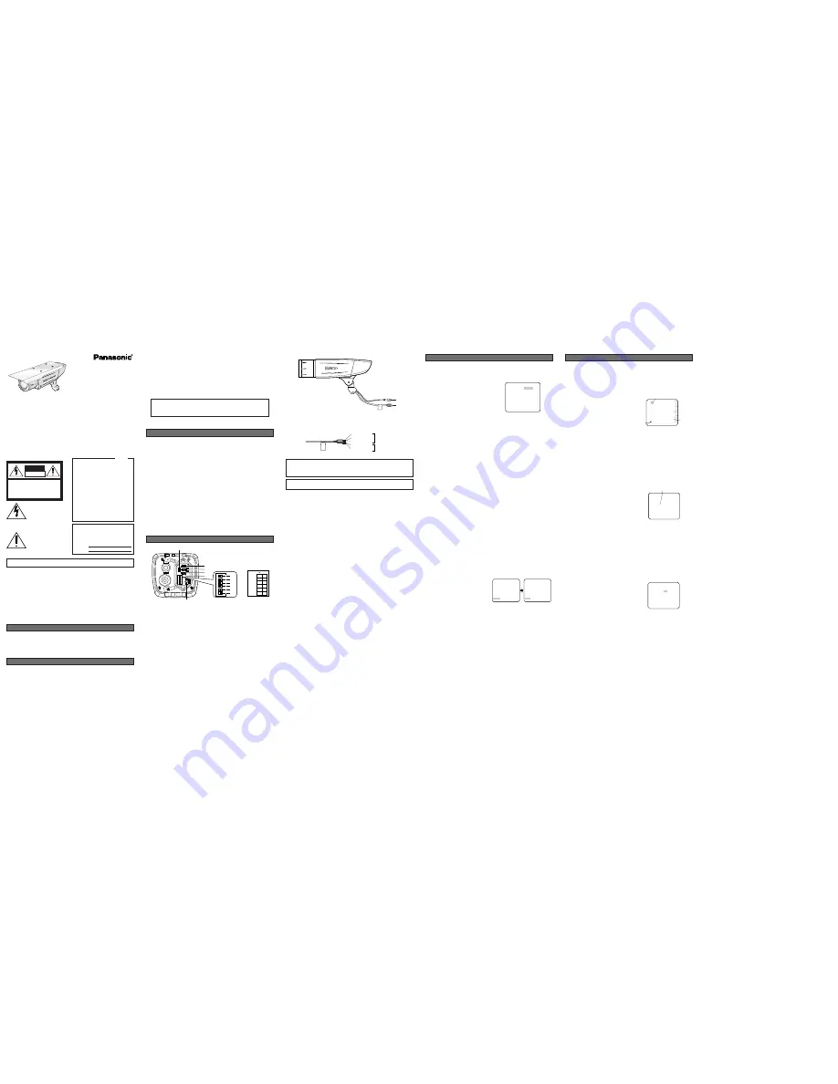
MAJOR OPERATING CONTROLS AND THEIR FUNCTIONS
q
LEFT Button
Moves the cursor to the left and selects items in the CAM SETUP menu.
w
UP Button
Moves the cursor upward and selects items in the CAM SETUP menu.
e
RIGHT Button
Moves the cursor to the right and selects items in the CAM SETUP menu.
r
Set Button
This button is used to activate an item selected in the CAM SETUP menu.
t
DOWN Button
Moves the cursor downward and selects items in the CAM SETUP menu.
y
SYNC switch (SW1)
Switches internal sync (INT) mode or line-lock (LL) mode. The factory default setting is INT.
u
UPSIDE DOWN switch (SW2)
Turn the picture upside down by selecting ON. The factory default setting is OFF.
i
AP GAIN switch (SW3)
Selects the aperture gain level to SHARP or SOFT. The factory setting is SHARP.
o
BW switch (SW4)
Switches to AUTO between color and black -and-white picture in response to light input. The
factory default setting is OFF.
!0
BW AUTO LEVEL switch (SW5)
Selects the illuminance level in LOW or HIGH mode for B/W. The factory default setting is HIGH.
!1
LED ON/OFF switch (SW6)
The factory default setting is ON.
!2
Monitor output Jack (3.5 Diam. Mini jack)
Connects the LCD monitor and such devices with 3.5 mm in diam. 2-pole plug for checking
images.
N0404-0
3TR002483AAA
Printed in Japan
Panasonic's WV-CW374 color digital camera introduces a new level of high picture quality and high
resolution through the use of a 1/3-inch interline transfer CCD image sensor having 768 horizontal
pixels (picture elements), and digital signal processing LSIs. This model offers cutting-edge tech-
nology for advanced video surveillance.
PREFACE
Caution:
Connect to 12 V DC (10.5 V-16 V) or 24 V AC 60 Hz (19.5 V-28 V) class 2 power sup-
ply only. Make sure to connect the grounding lead to the GND terminal when the
power is supplied from a 24 V AC 60 Hz power source.
Color CCTV Cameras
Operating Instructions
y
u
i
o
!0
!1
q
!2
r
t
e
w
ON
INT
1 SYNC
2 UPSIDE
DOWN
3 AP GAIN
4 BW
5 BW AUTO
LEVEL
6 LED
LL
OFF
ON
OFF
AUTO
LOW
HIGH
OFF
ON
SHARP SOFT
1
2
3
4
5
6
SD
II
WV-C
W37
4
Model No.
WV-CW374
WARNING:
All work related to the installation of this product should be made by qualified service personnel or
system installers.
Caution: For heater
Connect to 24 V AC 60 Hz (19.5 V-28 V) class 2 power supply only.
!4
Video output cable with BNC connector
Connects with the video connector of the monitor.
6. Never face the camera towards the sun.
Do not aim the camera at bright objects. Whether the camera is in use or not, never aim it at
the sun or other extremely bright objects. Otherwise, blooming or smear may be caused.
7. Do not operate the camera beyond the specified temperature, humidity or power source
ratings.
Use the camera at temperatures within –30 °C to +50 °C (–22 °F - 122 °F), and humidity below
90 %. The input power source is 12 V DC or 24 V AC 60 Hz.
8. Turn the circuit breaker off which supplies the camera with the power when abnormal
conditions are encountered.
Black (Live)
Blue (Neutral)
for camera
Green/Yellow (GND)
Brown (Live)
Gray (Neutral)
for heater
The exclamation point within an
equilateral triangle is intended to
alert the user to the presence of
important operating and mainte-
nance (servicing) instructions in the
literature accompanying the appli-
ance.
The lightning flash with arrowhead
symbol, within an equilateral trian-
gle, is intended to alert the user to
the presence of uninsulated "dan-
gerous voltage" within the product's
enclosure that may be of sufficient
magnitude to constitute a risk of
electric shock to persons.
SA 1966
SA 1965
CAUTION: TO REDUCE THE RISK OF ELECTRIC SHOCK,
DO NOT REMOVE COVER (OR BACK).
NO USER-SERVICEABLE PARTS INSIDE. REFER SER-
VICING TO QUALIFIED SERVICE PERSONNEL.
CAUTION
RISK OF ELECTRIC
SHOCK DO NOT OPEN
The serial number of this product may be found on
the top of the unit.
You should note the serial number of this unit in the
space provided and retain this instruction as a per-
manent record of your purchase to aid identification
in the event of theft.
Model No.
Serial No.
NOTE: This equipment has been tested and found
to comply with the limits for a Class A digital
device, pursuant to Part 15 of the FCC Rules.
These limits are designed to provide reasonable
protection against harmful interference when the
equipment is operated in a commercial environ-
ment. This equipment generates, uses, and can
radiate radio frequency energy and, if not installed
and used in accordance with the instruction manu-
al, may cause harmful interference to radio com-
munications.
Operation of this equipment in a residential area is
likely to cause harmful interference in which case
the user will be required to correct the interference
at his own expense.
FCC Caution: To assure continued compliance,
(example - use only shielded interface cables when
connecting to computer or peripheral devices). Any
changes or modifications not expressly approved
by the party responsible for compliance could void
the user’s authority to operate this equipment.
For U.S.A
Caution:
Before attempting to connect or operate this
product, please read the marking on the top.


