background image

Before attempting to connect or operate this product,

please read these instructions carefully and save this manual for future use.

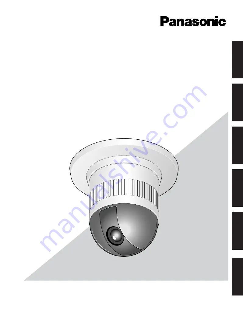
Colour CCTV Camera

Operating Instructions

Model Nos.

WV-CS570

WV-CS574E

ENGLISH

DEUTSCH

FRANÇAIS

ESP

AÑOL

IT

ALIANO

êìëëäàâ

Summary of Contents for WV-CS574E

Page 1: ...nect or operate this product please read these instructions carefully and save this manual for future use Colour CCTV Camera Operating Instructions Model Nos WV CS570 WV CS574E ENGLISH DEUTSCH FRANÇAIS ESPAÑOL ITALIANO êìëëäàâ ...

Page 2: ... coloured brown must be connected to the terminal in the plug which is marked with the letter L or coloured red CAUTION TO REDUCE THE RISK OF ELECTRIC SHOCK DO NOT REMOVE COVER OR BACK NO USER SERVICEABLE PARTS INSIDE REFER SERVICING TO QUALIFIED SERVICE PERSONNEL CAUTION RISK OF ELECTRIC SHOCK DO NOT OPEN CAUTION Before attempting to connect or operate this product please read the label on the su...

Page 3: ...r outlet consult an electrician for replacement of the obsolete outlet 10 Protect the power cord from being walked on or pinched particularly at plugs convenience receptacles and the points where they exit from the apparatus 11 Only use attachments accessories specified by the manufacturer 12 Use only with the cart stand tripod bracket or table specified by the manufacturer or sold with the appara...

Page 4: ...AL OR EXEMPLARY ARISING OUT OF OR RELATING TO THE PRODUCT 2 PERSONAL INJURY OR ANY DAMAGE CAUSED BY INAPPROPRIATE USE OR NEGLIGENT OPERATION OF THE USER 3 UNAUTHORIZED DISASSEMBLE REPAIR OR MODIFICATION OF THE PRODUCT BY THE USER 4 INCONVENIENCE OR ANY LOSS ARISING WHEN IMAGES ARE NOT DISPLAYED DUE TO ANY REASON OR CAUSE INCLUDING ANY FAILURE OR PROBLEM OF THE PRODUCT 5 ANY PROBLEM CONSEQUENTIAL I...

Page 5: ...manual camera move ment routines for automatic playback when they are needed For example you can teach the camera the movements of the people you want to monitor by replaying the stored parameters complicated move ments are done automatically Camera Position Memory The system can be configured with up to 32 camera positions A particular camera position can be selected and viewed by entering the ap...

Page 6: ...nction Do not operate the camera beyond the specified temperature humidity or power source ratings Do not use the camera in an extreme environment where high temperature or high humidity exists Do not place the camera near heat sources such as radiators stoves or other units that produce heat Use the camera under conditions where temperature is between 10 C 50 C 14 F 122 F preferably 40 C 104 F an...

Page 7: ...menu to execute the REFRESH operation page 50 If you are using a matrix switcher with a camera clean ing function WJ SX550C configure the matrix switch er Auto Cleaning settings so cleaning is performed once a day Downloading saving or uploading recovering camera preset data When downloading or uploading camera preset data aim the camera at static objects such as a wall without moving the camera a...

Page 8: ...eters DIP Switch 1 13 CAMERA INSTALLATION 14 Preparing the Camera and Decorative Cover for Side Cable Exit 14 Installing the Camera 14 UNINSTALLING THE CAMERA 16 Uninstalling the Camera 16 CONNECTIONS 17 RS485 SETUP 19 USING THE SETUP MENU 20 Setup Menu 20 Setup Menu Description 22 SETTING PROCEDURES 26 Menu Display 26 Preset Menu 26 Deleting Preset Positions 31 Home Position Setting HOME POSITION...

Page 9: ...1 is turned on If cleaning the slip ring does not eliminate poor picture quality and noise it could mean that the slip ring has reached the end of its service life Contact a qualified service person or system installer to have it replaced w e r t t q y u o i 0 WV CS570 WV CS574E q Alarm Input Connector w Alarm Output Connector e Video Output Connector r Data Port t Power Cable for WV CS570 t Power...

Page 10: ...nts of steam vapor and oil in flammable atmospheres other special environments Areas where radiation X rays strong electric waves or magnetism is generated At sea in coastal areas or in areas where corrosive gas is being generated Areas outside of the allowable ambient operating temperature range 10 C to 50 C 14 F to 122 F In a motor vehicle on a boat or other areas subject to strong vibration Thi...

Page 11: ...inside the camera and then replace the dome page 9 Ventilation holes DIP SWITCH SETTINGS In a configuration where the camera s RS485 data port is used for camera control pan tilt etc by the system con troller the camera s DIP switches must be configured to specify the unit number and communication parameters The camera mounting base needs to be removed to access the DIP switches See steps 1 to 3 o...

Page 12: ...DIP Switch 1 Unit Number DIP Switch 1 Unit Number 1 96 1 2 3 4 5 6 7 8 9 10 11 12 13 14 15 16 17 18 19 20 21 22 23 24 25 26 27 28 29 30 31 32 33 34 35 36 37 38 39 40 41 42 43 44 45 46 47 48 49 50 51 52 53 54 55 56 57 58 59 60 61 62 63 64 65 66 67 68 1 2 3 4 ON 5 6 7 8 1 2 3 4 ON 5 6 7 8 1 2 3 4 ON 5 6 7 8 1 2 3 4 ON 5 6 7 8 1 2 3 4 ON 5 6 7 8 1 2 3 4 ON 5 6 7 8 1 2 3 4 ON 5 6 7 8 1 2 3 4 ON 5 6 7 ...

Page 13: ... 19 Turning on power when this setting is selected causes the RS485 SET UP menu to appear during the initialization routine RS485 Communication Parameters DIP Switch 1 Configuring DIP Switch 1 as shown below resets communication parameters to their factory default settings You can then change the settings as desired Perform the following steps to use this setting 1 Turn off the camera and use DIP ...

Page 14: ...t in accordance with the instructions that come with it 1 Remove the fixing screw M3 6 that secures the camera to the mounting base Put the screw in a place where it will not become lost 2 Rotate the camera base unit in the direction indicat ed by the arrow and remove it 3 Using the camera mounting base as a template mark the locations of the four mounting holes on the ceiling If you are using the...

Page 15: ... Tighten the fixing screw M3 provided Notes 1 Tighten the camera fixing screw with a screw driver 2 Follow the instructions given here to ensure that the camera and camera mounting base are installed safely 3 When removing the camera from the camera mounting base loosen and press up the camera fixing screw M3 with a screwdriver 8 Fix the decoration cover to the camera mounting base a Sideway Cable...

Page 16: ...ovides double anchoring and you should use the following procedure to uninstall the cam era 1 Remove the fixing screw that secures the camera to the mounting base Put the screw in a place where it will not become lost 2 Remove the camera from the mounting base Rotate the camera in the direction indicated by the arrow and remove it 3 Remove the safety wire from the mounting base Camera Camera Mount...

Page 17: ...es See the reverse side of the cover page for main lead connection The coaxial cable length RG 59 U BELDEN 9259 for the connection is up to 1 200 meters 4 000 ft To VIDEO IN CAMERA IN Video output BNC plug Coaxial cable RS485 cable Data port BNC plug Alarm in Alarm out To sensors To indicators 24 V AC cable Note When powered up the unit performs a self check including one panning tilting zooming a...

Page 18: ...ctions Note Use a relay if the voltage or current of the connected device exceeds the ratings Red Data transmission Data reception Orange Yellow Green T B T A R B R A RS485 Connection Black Brown Red Orange Yellow Light blue or green Blue Purple Wire colour Function IN 1 GND IN 2 GND IN 3 GND IN 4 GND Alarm IN 8 pin ALARM OUT Connections Connect an external device for example a buzzer or lamp to t...

Page 19: ... to XON XOFF and then tilt the joy stick left or right to select an XON XOFF setting The factory default setting is NOT USE NOT USE Disables X ON X OFF data flow control USE Enables X ON X OFF data flow control 8 Move the cursor to WAIT TIME and then tilt the joy stick left or right to select a wait time setting The wait time is the time that the camera should wait before resending data when no re...

Page 20: ...n P 45 Electronic Sensitivity Enhancement P 45 Synchronization P 45 White Balance P 46 Motion Detector P 47 Auto Focus Setting P 48 Special 2 Menu P 49 RS 485 Setup P 19 Password Lock P 34 Preset No Setting P 26 Preset Setting Menu P 26 Auto Pan Setting P 32 INT Manual Selection P 45 LL Manual Selection P 45 VD2 Automatic Selection P 45 Manual Level Adjustment ATW1 ATW2 P 46 Manual Level Adjustmen...

Page 21: ...Check P 19 Stop Bit P 19 X On X Off P 19 Wait Time P 19 Alarm Data P 19 Delay Time P 19 Light Control Setting P 29 To Restore the Camera Default Position P 50 Camera Resetting P 50 Zone Number Selection P 35 Zone Parameter Setting P 35 Setting for ON USER P 37 Setting for ON NESW P 37 Area Title Display P 38 Learning Display P 39 Alarm IN OUT Setting P 40 Cleaning Display P 41 Scene File Setting P...

Page 22: ... to other than OFF Activates the auto mode HP Shifts the camera direction to the home position AP Starts the auto pan function SQ Starts the sequence function SR Starts the sort function PT Starts the patrol function See page 31 for the setting Auto Mode AUTO MODE The auto mode is used for setting the movement of the camera You can select one of four automatic operation modes and one manual operat...

Page 23: ...s selected When a preset positioning sequence is completed while AUTO MODE is set to SEQ When a preset positioning sequence is completed while AUTO MODE is set to SORT Positioning is completed at the HOME position in the SELF RETURN mode Positioning is completed in the ALARM IN mode When positioning to the starting point is completed while AUTO MODE is set to AUTO PAN When positioning to the start...

Page 24: ... resolution will be lowered in this mode If the iris opening is too small the SENS UP AUTO mode will not function 6 Synchronization SYNC You can select the internal sync INT mode or the line lock sync LL mode Additionally this model accepts the VD2 signal from a specified component Whenever the VD2 signal is supplied to this camera the camera automatically switches to the VD2 sync mode When you se...

Page 25: ...his menu allows you to adjust and set up the fol lowing items and functions chroma level aperture level and pedestal level You can also reset your parameters to the factory default settings See page 49 for the setting 11 Self diagnosis Function If the camera continues operating abnormally for 30 seconds or more due to such accident as external noise the camera will automatically reset its power In...

Page 26: ... 25 29 ID DOOR RET 3 7 11 15 19 23 27 31 4 8 12 16 20 24 28 32 SETTING PROCEDURES The following setting procedures are described on the assumption that this model is used in combination with WJ SX150 Matrix Switcher and WV CU650 System Controller Menu Display Setup Menu Display WV CU650 1 Select the camera you want to set up this camera and the monitor where you want to display the setup menu 2 Pr...

Page 27: ...the pan offset function is used to adjust its positions to be the same as before except patrol setting The system controller can download or upload the preset position data Caution The preset data for other cameras WV CS654 for example is incompatible with WV CS570 574E WV CS570 574E s preset data will be destroyed if you upload the conventional data If this happened reset the WV CS570 574E to the...

Page 28: ...EFGHIJKLM NOPQRSTUVWXYZ ÄÜÖÆÑÅ SPACE COPY POSI RET RESET DOOR PRESET NO 1 0123456789 ABCDEFGHIJKLM NOPQRSTUVWXYZ ÄÜÖÆÑÅ SPACE COPY POSI RET RESET DOOR 28 4 To Set the Lens Zoom and Focus Positions 1 Move the cursor to PUSH SET for ZOOM FOCUS and press the CAM SET button The ZOOM FOCUS setting menu appears 2 Select zoom focus positions with the joystick and then press the CAM SET button The positio...

Page 29: ...PY POSI RET RESET DOOR To Enter the Next ID without Returning to the Preset Setting Menu 1 In the preset ID setting menu move the cursor to the top line and select a desired position number with the joystick 2 Enter copy change or delete the ID as described above To Return to the Preset Setting Menu Move the cursor to RET and press the CAM SET button Light Control Setting ALC MANUAL 1 Move the cur...

Page 30: ... 2 6 10 14 18 22 26 30 1 5 9 13 17 21 25 29 ID DOOR RET 3 7 11 15 19 23 27 31 4 8 12 16 20 24 28 32 30 Dwell Time DWELL TIME Move the cursor to DWELL TIME and set a dwell time with the joystick The factory default setting is 10S Dwell time changes as follows S stands for second s and MIN stands for minute s Scene File Setting SCENE FILE 1 To set a scene file number Move the cursor to SCENE FILE an...

Page 31: ...tion Setting HOME POSITION 1 To set a position number for the home position Move the cursor to HOME POSITION and select a desired position number with the joystick 2 Select OFF if you are not using the home position function Self Return Setting SELF RETURN You can set a return time and one of operation modes with this menu 1 Move the cursor to SELF RETURN select a return time from among the follow...

Page 32: ...PAN POSITION SPEED ENDLESS DWELL TIME PAN LIMIT ZOOM LIMIT RET START END L H OFF 1S OFF OFF AUTO PAN POSITION SPEED ENDLESS DWELL TIME PAN LIMIT ZOOM LIMIT RET START END L H OFF 1S OFF OFF AUTO PAN POSITION SPEED ENDLESS DWELL TIME PAN LIMIT ZOOM LIMIT RET START END L H ON 1S OFF OFF 32 Auto Mode Selection AUTO MODE 1 To set auto mode Move the cursor to AUTO MODE and select a mode with the joystic...

Page 33: ...OOM LIMIT ZOOM RET PUSH SET 2 Move the cursor to ZOOM press the CAM SET button move the joystick to settle the ZOOM position and return to the AUTO PAN menu The manual zoom operation is not available in the TELE direction beyond the settled zoom position OFF Does not limit the manual zoom operation Notes When the panning tilting zooming or focusing in the SEQ SORT or PATROL mode is controlled manu...

Page 34: ...ns the auto panning function to the button SEQ Assigns the SEQUENCE function to the but ton SORT Assigns the SORT function to the button PATROL Assigns the PATROL PLAY function to the button Note AUTO PAN LED on the controller does not light if something other than AUTO PAN is assigned AUTO PAN does not stop with the AUTO PAN button If PASSWORD LOCK is set to ON you cannot operate AUTO PAN SEQ SOR...

Page 35: ...menu without changing the password move the cursor to RET and press the CAM SET button NEW PASSWORD 0 1 2 3 4 5 6 7 8 9 OK RESET RET Special 1 Menu Setting SPECIAL 1 Privacy Zone PRIVACY ZONE Up to 8 unwanted zones can be masked on the monitor screen 1 Move the cursor to PRIVACY ZONE and select ON or OFF with the joystick Press the CAM SET button to display the ZONE NUMBER setting menu ON Preset p...

Page 36: ...ONE OFF PROPO P T ON AREA TITLE ON USER PATROL STOP ALARM IN OUT CLEANING OFF EL ZOOM ON PRESET ALM OFF IMAGE HOLD OFF TILT ANGLE 0 RET 36 When 5 privacy zones or more are framed on the displayed screen in the same time the whole screen will be masked In this case diminish the number of the zones and set the privacy zones larger The privacy zone may appear on the monitor screen depending on the di...

Page 37: ... FOCUS POSI N RET PUSH SET PUSH SET PUSH SET DIRECTION NESW PAN TILT ZOOM FOCUS POSI U TILT D L PAN R N RET 3 Move the cursor to PUSH SET for ZOOM FOCUS and press the CAM SET button ZOOM FOCUS is highlighted and U ZOOM D L FOCUS R appears 4 Adjust the zoom or focus with the joystick 5 Move the cursor to POSI O and press the CAM SET button The area title position appears on the monitor screen If ne...

Page 38: ... BALANCE IMAGE HOLD AREA TITLE FLOOR 1 NORTH SPECIAL 1 PRIVACY ZONE OFF PROPO P T ON AREA TITLE ON USER PATROL PLAY ALARM IN OUT CLEANING OFF EL ZOOM ON PRESET ALM OFF IMAGE HOLD OFF TILT ANGLE 0 RET 38 1 To select a camera direction move the cursor to the desired number and press the CAM SET button The direction menu of the selected number appears 2 Adjust PAN TILT ZOOM FOCUS and display the posi...

Page 39: ...e start the patrol learn function again from the starting point LEARN also stops 1 minute after starting if the memory is full Auto refreshing may be activated in the patrol play mode or the auto mode to calibrate the lens position Patrol Play with a Controller Having the PATROL Button 1 Press the PATROL PLAY button The camera turns to the starting point and reproduces the operations stored in the...

Page 40: ...r it turns to a preset position OFF The camera does not send an output signal Notes The camera ignores alarm inputs during manual operation To download or upload preset data to the system controller select OFF 40 Alarm Input Output ALARM IN OUT Move the cursor to ALARM IN OUT and press the CAM SET button The ALARM IN OUT submenu appears Note While the camera is in the AF mode or the lens moves bet...

Page 41: ...ed by the electronic zoom func tion may be inferior in picture quality to a non magnified one The electronic zoom does not function in the pre set position setting mode When trying to set preset positions directly from the WV CU360 System Controller while ON is set for the electronic zoom function and the dis played scene is magnified at more than x22 the INHIBIT indication will be displayed In th...

Page 42: ...UTO L OFF SET UP CAMERA ID ALC MANUAL SHUTTER AGC SENS UP SYNC WHITE BAL MOTION DET AF MODE RET SPECIAL2 ON ALC AUTO ON MID OFF INT ATW1 OFF AUTO L 42 Image Hold IMAGE HOLD The camera picture remains as a still image on the monitor screen until the camera reaches the preset position This function is useful for surveillance via local area network 1 Move the cursor to IMAGE HOLD and select ON or OFF...

Page 43: ... ID 0123456789 ABCDEFGHIJKLM NOPQRSTUVWXYZ ÄÜÖÆÑÅ SPACE POSI RET RESET CAM1 Light Control Setting ALC MANUAL 1 Move the cursor to ALC MANUAL and select ALC or MANUAL with the joystick When you select ALC set backlight compensation Note The backlight compensation submenu associat ed with this menu is described separately and should be set up after installing the camera at the site and observing the...

Page 44: ...CAMERA ID ALC MANUAL SHUTTER AGC SENS UP SYNC WHITE BAL MOTION DET AF MODE RET SPECIAL2 OFF ALC AUTO ON MID OFF INT ATW1 OFF AUTO L OFF 1 50 1 120 AUTO 1 10 000 1 4 000 1 2 000 1 1 000 1 250 1 500 44 2 ALC Mode with BLC OFF 1 Move the cursor to BLC and select OFF When you select MANUAL BLC is not available MASK SET appears on the menu 2 Move the cursor to MASK SET and press the CAM SET button The ...

Page 45: ...ODE RET SPECIAL2 OFF ALC AUTO ON MID OFF INT ATW1 OFF AUTO L X2 AUTO OFF X4 AUTO X6 AUTO X10 AUTO X16 AUTO X32 AUTO X2 FIX X6 FIX X10 FIX X16 FIX X32 FIX X4 FIX OFF Synchronization SYNC Move the cursor to SYNC and select LL or INT with the joystick Important Notices 1 The priorities of SYNC modes are assigned as fol lows 1 Multiplexed vertical drive VD2 highest priority 2 Line lock LL 3 Internal s...

Page 46: ...on of WV CU650 For WV RM70 press the right and left switches simultaneously COARSE is preset to zero crossing of the AC line phase If the AC line phase contains spike noise etc the vertical phase of the video output signal may be disturbed White Balance WHITE BAL 1 Auto Tracing White Balance Mode ATW1 ATW2 1 Move the cursor to WHITE BAL and select ATW1 with the joystick The white balance of the ca...

Page 47: ...ask ing operations 4 After masking areas press the MON ESC button The MOTION DETECT menu appears on the monitor screen 5 Move the cursor to ALARM and select ON or OFF with the joystick ON The alarm signal is supplied while the display mode is activated OFF The alarm signal is not supplied while the dis play mode is activated 6 Move the cursor to DISPLAY MODE Press the CAM SET button to see the pre...

Page 48: ...t 5 No centre objects and sloping objects 6 Far and near objects on the screen SET UP CAMERA ID ALC MANUAL SHUTTER AGC SENS UP SYNC WHITE BAL MOTION DET AF MODE RET SPECIAL2 OFF ALC AUTO ON MID OFF INT ATW1 OFF AUTO L AUTO S AUTO M AUTO L MANUAL L MANUAL M MANUAL S 48 10 Move the cursor to RET and press the CAM SET button to return to SET UP Important Notices The motion detection should meet the f...

Page 49: ...LOW2 PIX OFF REFRESH CAMERA RESET RET NORMAL Sets the horizontal resolution to more than 480 lines HIGH Sets the horizontal resolution to more than 510 lines Note After selecting HIGH noise may increase when the SENS UP function is activated under low illu mination Digital Noise Reduction DNR DNR may be used to improve quality under low light conditions There are 4 levels of DNR which may be selec...

Page 50: ...registered password will not be reset For WV RM70 hold down the right left and set switches simultaneously for 2 seconds or more For WV CU161C hold down the 4 5 and 6 keys simultaneously for 2 seconds or more The ALL RESET indication will be displayed Note In case of performing this operation on the condition that the cursor is positioned on other than CAMERA RESET you cannot perform the operation...

Page 51: ...OFF INT ATW1 OFF AUTO L I I I NORMAL LOW2 Item Setting Menu PRESET MENU AUTO PAN SCENE FILE RS485 SET UP ALARM IN OUT PRESET ID ALC MANUAL BLC DWELL TIME SCENE FILE PRESET SPEED SPEED PAN LIMIT ENDLESS DWELL TIME UNIT NUMBER SUB ADDRESS BAUD RATE DATA BIT PARITY CHECK STOP BIT XON XOFF WAIT TIME ALARM DATA DELAY TIME ALARM IN1 ALARM IN2 ALARM IN3 ALARM IN4 CNT CLS 1 TIME OUT CNT CLS 2 COAX ALM OUT...

Page 52: ...up to 16 characters ON OFF ON OFF up to 8 zones ON OFF LEARN PLAY STOP up to 60 seconds ON OFF Image Hold ON OFF Auto Mode Auto Pan Key Digital Flip Camera ID Motion Detector Privacy Zone Proportional PAN TILT Patrol Dimensions 24 V AC 50 Hz 220 V 240 V AC 50 Hz 120 D x 191 H mm 4 3 4 D x 7 1 2 H approx 2 kg 4 4 lbs 10 C 50 C 14 F 122 F Recommended operating temperature 35 C 95 F or less 13 W 15 W...

Page 53: ...to pan manual approx 0 1 s 120 s 8 steps 16 steps 64 steps sequence position maximum approx 300 s 0 to 180 5 to 185 at 5 tilt angle setting manual sequential position sort position manual approx 0 1 s 120 s 8 steps 16 steps 64 steps sequential position maximum approx 300 s pan tilt lens 32 preset positions home position Panning Angle Setting Panning Mode Panning Speed Tilting Range Tilting Mode Ti...

Page 54: ...O PAN OFF 6 7 CAM FUNCTION Increases AUTO PAN speed one step 6 8 CAM FUNCTION Decreases AUTO PAN speed one step 6 9 CAM FUNCTION Sets AUTO PAN start point 7 0 CAM FUNCTION Sets AUTO PAN end point 7 1 CAM FUNCTION AUTO MODE OFF 7 2 CAM FUNCTION AUTO MODE SEQ ON 7 3 CAM FUNCTION AUTO MODE SORT ON 7 4 CAM FUNCTION Reverses AUTO PAN range 7 6 CAM FUNCTION ENDLESS ON 7 7 CAM FUNCTION ENDLESS OFF 7 8 CA...

Page 55: ...sensitivity enhancement FIX one step 1 8 1 CAM FUNCTION SENS UP AUTO ON 1 8 2 CAM FUNCTION SENS UP AUTO OFF 1 8 3 CAM FUNCTION Increases electronic sensitivity enhancement AUTO one step 1 8 4 CAM FUNCTION Decreases electronic sensitivity enhancement AUTO one step 1 8 5 CAM FUNCTION Increases line lock phase FINE one step 1 8 6 CAM FUNCTION Decreases line lock phase FINE one step 1 8 7 CAM FUNCTION...

Page 56: ...r system con troller Is the lens iris open Is the dome cover or lens of the camera dirty If so clean them The slip ring may be dirty Do you have the cleaning function turned on Check the white balance setting Is FIX selected for the electronic sensitivity enhancement SENS UP setting Is the lens iris closed Execute the iris reset from the system controller you are using Is the camera set up for a f...

Page 57: ...work The camera movement modes OFF SEQ SORT AUTO PAN PATROL do not work The camera movement mode OFF SEQ SORT AUTO PAN PATROL setting changes Camera position is different from the preset position set ting Is the camera connected correctly See the operat ing instructions that come with the system controller you are using The camera has a pan limit function Check the PAN LIMIT settings 33 The motor ...

Page 58: ...ipment private households This symbol on the products and or accompanying documents means that used electrical and electronic products should not be mixed with general household waste For proper treatment recovery and recycling please take these products to designated collection points where they will be accepted on a free of charge basis Alternatively in some countries you may be able to return y...

Page 59: ......

Page 60: ... Osaka Japan http www panasonic co jp global Printed in Japan Gedruckt in Japan Imprimé au Japon Impreso en Japón Stampato in Giappone 2005 Matsushita Electric Industrial Co Ltd All Rights Reserved N0405 1055 3TR003480BAA ç ÔÂ Ú ÌÓ üÔÓÌËË ...

Reviews: