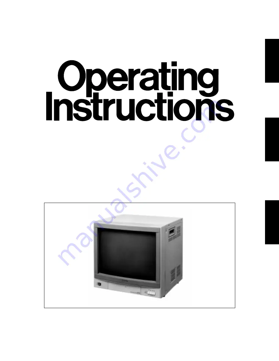
Colour Monitor
WV-CM2000
Before attempting to connect or operate this product, please read these instructions completely
DEUTSCH
FRANÇAIS
ENGLISH
D
Page 1: ...Colour Monitor WV CM2000 Before attempting to connect or operate this product please read these instructions completely DEUTSCH FRANÇAIS ENGLISH D ...
Page 2: ...NSERTED INTO ANY 13 AMP SOCKET If a new plug is to be fitted please observe the wiring code as shown below If in any doubt please consult a qualified electrician WARNING This apparatus must be earthed IMPORTANT The wires in this mains lead are coloured in accordance with the follow ing code Green and yellow Earth Blue Neutral Brown Live As the colours of the wire in the mains lead of this applianc...
Page 3: ...ut Selectable of 1 4 channel for input and output signal PRECAUTIONS Do not block the ventilation slots Do place the video monitor at least 5cm 2 apart from the wall Do not expose the monitor to water or moisture Do not operate the monitor if it becomes wet Do take immediate action if ever the monitor does become wet Turn power off and refer service person nel Moisture can damage the monitor and a...
Page 4: ... 2000 q w e r t y u i o 0 1 2 3 5 66 7 4 8 9 75Ω 75Ω 75Ω 75Ω Hiz OUT S VIDEO IN AUDIO IN INPUT 4 OUT OUT VIDEO IN AUDIO IN INPUT 2 OUT OUT IN STAND BY Hiz Hiz OUT S VIDEO IN AUDIO IN INPUT 3 OUT OUT VIDEO IN AUDIO IN INPUT 1 OUT Hiz FOCUS Hiz OUT S VIDEO IN AUDIO IN INPUT 4 OUT OUT VIDEO IN AUDIO IN INPUT 2 OUT OUT IN STAND BY Hiz 75Ω 75Ω 75Ω 75Ω Hiz OUT S VIDEO IN AUDIO IN INPUT 3 OUT OUT VIDEO I...
Page 5: ...lly 7 Horizontal Hold Control H HOLD This control is used to lock the picture in horizontally 8 Tint Control TINT Turn this control clockwise for purplish colour of the picture and turn this counterclockwise for greenish colour of the picture 9 Tint Subcontrol 10 Colour Control COLOUR Turn this control clockwise to increase the picture colour and turn this control counterclockwise to decrease the ...
Page 6: ...te PAL NTSC M NTSC video signal 33 Video Output Connector INPUT 2 VIDEO OUT The video input signal connected to the Video Input Connector 32 is looped through to this connector 34 Video Termination Switch INPUT 2 75Ω Hi z When bridging or looping through the video signal set this switch to Hi z position and other cases this switch should be set to 75Ω position 35 Audio Input Connector INPUT 2 AUDI...
Page 7: ... hooked up in this configura tion before signal loss occurs Total cable length should not exceed 150m 3 Wiring Precautions Do not bend coaxial cable into a curve whose radius is smaller than 10 times of its diameter Never crush or pinch the cable All these will change the impedance of the cable and cause poor picture quality Type of RG 59 U RG 6U RG 11 U RG 15 U coaxial cable 3C 2V 5C 2V 7C 2V 10C...
Page 8: ...Input Connector 42 on the second monitor and continue until all monitors are connected 3 Audio Circuit Signal Connect the coaxial cable between the Video or S Video Output connector of VTR or camera and the S Video Video Input Connector 22 27 32 or 37 on this monitor Connect the audio cable between the Audio Output Connector of VTR and the Audio Input Connector 25 30 35 or 40 of this monitor and c...
Page 9: ... OFF ON NARROW WIDE AFC 3 58 TRAP PICTURE TINT COLOUR BRIGHT CONTRAST PICTURE AUDIO MIN MAX FOCUS Hiz OUT S VIDEO IN AUDIO IN INPUT 4 OUT OUT VIDEO IN AUDIO IN INPUT 2 OUT OUT IN STAND BY 75Ω 75Ω 75Ω 75Ω Hiz Hiz OUT S VIDEO IN AUDIO IN INPUT 3 OUT OUT VIDEO IN AUDIO IN INPUT 1 OUT Hiz 500 19 11 16 49 1 13 16 500 19 11 16 460 18 1 8 14 9 16 ...
Page 10: ...l Size 51 cm 20 1 16 diagonal Audio Input Output 8dB Hi z Speaker Output 1 3 watts Resolution 500 lines or more at centre Sweep Linearity Horizntal 5 or less Vertical 5 or less Sweep Giometory 2 or less Stand by Manual External control AFC Speed Short Long switchable 3 58 MHz Trap On Off switchable Picture Selection Narrow Wide switchable Ambient Operating Temperature 10 C 50 C 14 F 122 F Ambient ...
Page 11: ...ieses Gerätes in den dafür vorgesehenen Raum eintragen und diese Anleitung als Kaufsunterlage aufbewahren um im Falle eines Diebstahls die ldentifizierung zu erleichtern Modellnummer Fabriknummer WARNUNG UM DIE GEFAHR VON BRAND ODER STROMSCHLAG ZU VERHÜTEN DIESES GERÄT WEDER REGEN NOCH FEUCHTIGKEIT AUSSETZEN WARNUNG WEDER DECKEL NOCH RÜCKPLATTE ABNEHMEN UM DIE GEFAHR EINES ELEKTRISCHEN SCHLAGS ZU ...
Page 12: ...e 1 4 für Eingangs und Ausgangssignale wählbar VORSICHTSMASSNAHMEN Niemals die Belüftungsschlitze abdecken Den Video Monitor so aufstellen daß ein Abstand von mindestens 5 cm zur Wand eingehalten wird Den Monitor niemals Wasser oder Feuchtigkeit ausset zen Den Monitor nicht betreiben wenn dieser naß wird Falls der Monitor naß wird sofort geeignete Gegenmaß nahmen treffen Die Stromversorgung aussch...
Page 13: ...CM 2000 q w e r t y u i o 0 1 2 3 5 66 7 4 8 9 75Ω 75Ω 75Ω 75Ω Hiz OUT S VIDEO IN AUDIO IN INPUT 4 OUT OUT VIDEO IN AUDIO IN INPUT 2 OUT OUT IN STAND BY Hiz Hiz OUT S VIDEO IN AUDIO IN INPUT 3 OUT OUT VIDEO IN AUDIO IN INPUT 1 OUT Hiz FOCUS Hiz OUT S VIDEO IN AUDIO IN INPUT 4 OUT OUT VIDEO IN AUDIO IN INPUT 2 OUT OUT IN STAND BY Hiz 75Ω 75Ω 75Ω 75Ω Hiz OUT S VIDEO IN AUDIO IN INPUT 3 OUT OUT VIDEO...
Page 14: ...WIDE NARROW Diese Position wählen wenn die Video quelle eine Kamera mit hoher Auflösung oder dgl ist WIDE Diese Position wählen wenn die Videoquelle ein Videorecorder mit niedriger Auflösung ist 6 Vertikaler Bildfangregler V HOLD Dieser Regler wird verwendet um ein vertikal durch laufenden Bild zu stebilisieren 7 Horizontaler Bildfangregler H HOLD Dieser Regler wird verwendet ium das Bild horizont...
Page 15: ...Hi z Für das Überbrücken oder Durchschleifen des des Video Signals ist dieser Schalter auf die Position Hi z einzustellen für andere Fälle sollte dieser Schalter auf die Position 75Ω eingestellt werden 30 Audio Eingangssteckverbinder INPUT 3 AUDIO IN Das 8dB Hi z Audio Signal kann an diesen Ein gangssteckverbinder angelegt werden 31 Audio Ausgangssteckverbinder INPUT 3 AUDIO OUT Das an den Audio E...
Page 16: ...es Kabels geändert was zu einer schlechten Bildqualität führt Typ des RG 59 U RG 6U RG 11 U RG 15 U Koaxial Kabels 3C 2V 5C 2V 7C 2V 10C 2V Empfohlene ft 825 1 650 1 980 2 640 max Kabellänge m 250 500 600 800 Vorsicht Bas als Zubehör mitgelieferte Netzkabel ist für eine Netzspannung von 220 bis 240 V ausgelegt 41 Audio Ausgangssteckverbinder INPUT 1 AUDIO OUT Das an den Audio Eingangssteckverbinde...
Page 17: ...zweiten Monitors verbinden Das Herstellen dieser Anschlüsse sinngemäß fortsetzen bis alle Monitore miteinander verbunden sind Den S Video oder Video Abschluß schalter 24 29 34 oder 39 des ersten Monitors oder der dazwis chenliegenden Monitore auf die Position Hi z ein stellen Dann den S Video oder Video Abschluß schalter 24 29 34 oder 39 des letzten Monitors auf die Position 75Ω einstellen Ein Koa...
Page 18: ...RROW WIDE AFC 3 58 TRAP PICTURE TINT COLOUR BRIGHT CONTRAST PICTURE AUDIO MIN MAX FOCUS Hiz OUT S VIDEO IN AUDIO IN INPUT 4 OUT OUT VIDEO IN AUDIO IN INPUT 2 OUT OUT IN STAND BY 75Ω 75Ω 75Ω 75Ω Hiz Hiz OUT S VIDEO IN AUDIO IN INPUT 3 OUT OUT VIDEO IN AUDIO IN INPUT 1 OUT Hiz 16 MASSZEICHNUNG Einheit mm 500 49 460 14 500 ...
Page 19: ...iagonale Tatsächliche Bildgröße 51 cm 20 1 16 Zoll Diagonale Audio Eingang Ausgang 8 dB Hiz Lautsprecher Ausgang 1 3 Watt Auflösung 500 Zeilen oder mehr in Bildmitte Ablenklinearität Horizontal 5 oder weniger Vertikal 5 oder weniger Ablenkgeometrie 2 oder weniger Bereitschaft Manuelle externe Steuerung AFC Zeit Kurz lang umschaltbar 3 58 MHz Trap Ein Aus umschaltbar Bildwahl schmal breit umschaltb...
Page 20: ... à caractère important dans la brochure qui accompagne l appareil Le numéro de série de l appareil se trouve sur la plaque de fond Nous vous conseillons de relever le numéro de série de votre appareil dans l espace réservé ci dessous et de con server précieusement votre notice d instructions en tant que justificatif d achat aux fins d identification en cas de vol No de modèle No de série Cet appar...
Page 21: ...nce admissible maximum de haut parleur de 1 3 W Sélection des canaux 1 à 4 pour les signaux d entrée et de sortie MESURES DE PRÉCAUTION Ne pas obturer les ouvertures d aération Ne pas approcher le moniteur vidéo couleur plus près que 5 cm d un mur Ne jamais exposer le moniteur vidéo couleur à la pluie ni à l humidité Ne jamais mettre l appareil en marche s il a été mouillé Prendre immédiatement le...
Page 22: ...2000 q w e r t y u i o 0 1 2 3 5 66 7 4 8 9 75Ω 75Ω 75Ω 75Ω Hiz OUT S VIDEO IN AUDIO IN INPUT 4 OUT OUT VIDEO IN AUDIO IN INPUT 2 OUT OUT IN STAND BY Hiz Hiz OUT S VIDEO IN AUDIO IN INPUT 3 OUT OUT VIDEO IN AUDIO IN INPUT 1 OUT Hiz FOCUS Hiz OUT S VIDEO IN AUDIO IN INPUT 4 OUT OUT VIDEO IN AUDIO IN INPUT 2 OUT OUT IN STAND BY Hiz 75Ω 75Ω 75Ω 75Ω Hiz OUT S VIDEO IN AUDIO IN INPUT 3 OUT OUT VIDEO IN...
Page 23: ...NT Tourner cette commande dans le sens des aiguilles d une montre pour accentuer le violet et la tourner dans le sens inverse des aiguilles d une montre pour l atténuer 9 Réglage secondaire de teinte 10 Réglage de couleur COLOUR Tourner cette commande dans le sens des aiguilles d une montre pour accentuer la couleur et la tourner dans le sens inverse des aiguilles d une montre pour l atténuer 11 R...
Page 24: ...sortie vidéo INPUT 2 VIDEO OUT Le signal d entrée vidéo appliqué au connecteur d en trée vidéo 32 est bouclé par l intermédiaire de ce connecteur 34 Commutateur de terminaison vidéo INPUT 2 75Ω Hi z Quand un pontage ou un bouclage est réalisé par l in termédiaire du signal vidéo placer le commutateur en position Hi z et dans tous les autres cas en position 75Ω 35 Connecteur d entrée audio INPUT 2 ...
Page 25: ...s vidéo peut être utilisé avec cette configuration avant qu une perte de signal se produise La longueur totale du câble ne doit pas dépasser 150 m 3 Mesures de précaution à prendre avec les câbles Ne jamais former de courbure avec les câbles ni former de boucle dont le rayon est inférieur à 10 fois son diamètre Ne jamais écraser ni pincer le câble Toutes ces conditions font varier l impédance du c...
Page 26: ...entrée S vidéo ou vidéo 22 27 32 ou 37 de ce moniteur vidéo couleur Raccorder le câble coaxial entre le connecteur de sor tie vidéo S vidéo vidéo 23 28 33 ou 38 du pre mier moniteur vidéo couleur et le connecteur d entrée S vidéo vidéo 22 27 32 ou 37 du deuxième moniteur vidéo couleur et continuer les branchements ainsi jusqu à ce que tous les moniteurs vidéo couleur soient branchés Commuter le co...
Page 27: ...D ON OFF LONG SHORT OFF ON NARROW WIDE AFC 3 58 TRAP PICTURE TINT COLOUR BRIGHT CONTRAST PICTURE AUDIO MIN MAX FOCUS Hiz OUT S VIDEO IN AUDIO IN INPUT 4 OUT OUT VIDEO IN AUDIO IN INPUT 2 OUT OUT IN STAND BY 75Ω 75Ω 75Ω 75Ω Hiz Hiz OUT S VIDEO IN AUDIO IN INPUT 3 OUT OUT VIDEO IN AUDIO IN INPUT 1 OUT Hiz 500 49 460 14 500 ...
Page 28: ...iagonal Surface visuelle réelle 51 cm 20 1 16 en diagonal Entrée sortie audio 8 dB Hi z Sortie haut parleur 1 3 watts Résolution 500 lignes ou mieux mesuré au centre Linéarité de balayage Horizontale 5 ou moins Verticale 5 ou moins Géométrie de balayage 2 ou moins Veille Commande manuelle extérieure Vitesse de CAF Commutable lente rapide Filtre 3 58 MHz Commutable marche arrêt Sélection d image Co...
Page 29: ...Matsushita Electric Industrial Co Ltd Central P O Box 288 Osaka 530 91 Japan N0594 3125 YWV8QA3284DN Printed in Japan N 13 Gedruckt in Japan Imprimé au Japon ...