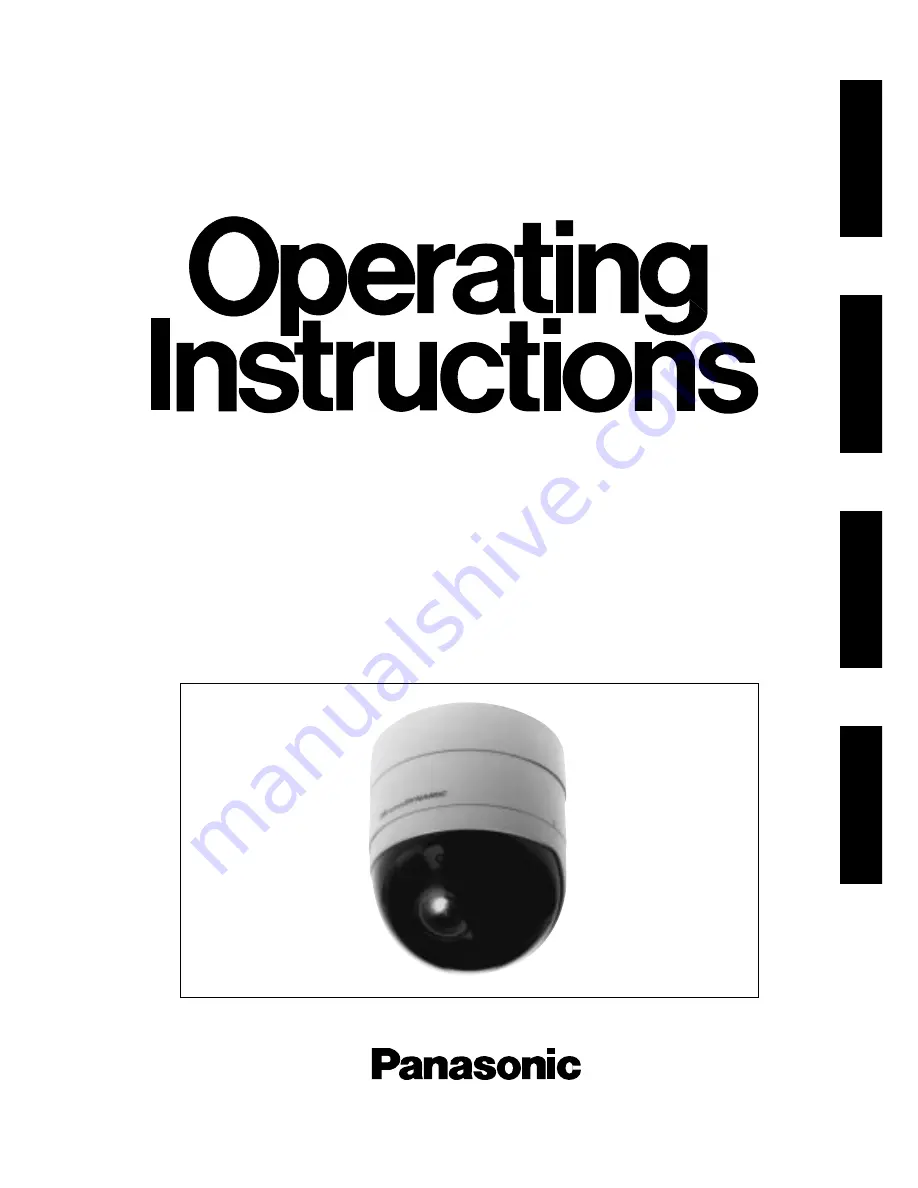
Colour CCTV Camera
WV-CF250
WV-CF254
Before attempting to connect or operate this product, please read these instructions completely
ENGLISH
DEUTSCH
FRANÇAIS
ESP
AÑOL
Page 1: ...Colour CCTV Camera WV CF250 WV CF254 Before attempting to connect or operate this product please read these instructions completely ENGLISH DEUTSCH FRANÇAIS ESPAÑOL ...
Page 2: ...itute a risk of electric shock to per sons The exclamation point within an equilat eral triangle is intended to alert the user to the presence of important operating and maintenance servicing instruc tions in the literature accompanying the appliance The serial number of this product may be found on the top of the unit You should note the serial number of this unit in the space provided and retain...
Page 3: ...nsvar för att den produkt till vilken denna deklaration hänvisar är i överensstämmelse med standarddokument eller andra normativa dokument som framstölls i Direktiv 73 23 EEC och 89 336 EEC Ilmoitamme yksinomaisella vastuullamme että tuote jota tämä ilmoitus koskee noudattaa seuraavia standardeja tai muita ohjeellisia asiakirjoja jotka noudattavat direktiivien 73 23 EEC ia 89 336 EEC säädöksiä Vi ...
Page 4: ... FEATURES 1 Do not attempt to disassemble the camera To prevent electric shock do not remove screws or covers There are no user serviceable parts inside Ask a qualified service person for servicing 2 Handle the camera with care Do not abuse the camera Avoid striking shaking etc The camera could be damaged by improper handling or storage 3 Do not expose the camera to rain or moisture or try to oper...
Page 5: ... 3 MAJOR OPERATING CONTROLS AND THEIR FUNCTIONS OPEN LOCK OPEN LOCK LEFT RIGHT SET DOWN UP ...
Page 6: ...or the wall Caution Connect to 24 V AC 19 5 V 28 V class 2 power supply only Make sure to connect the grounding lead to the GND terminal when the power is supplied from a 24 V AC power source q Panning Table This adjusts the panning angle of the camera w Camera Head This adjusts the tilting angle of the camera e Focus Ring This adjusts the focus r Zoom Ring This adjusts the angle of view t D Down ...
Page 7: ... the individual conductors for clamping Use MOLEX band tool part number 57027 5000 for UL Style Cable UL1015 or 57026 5000 for UL Style UL 1007 for clamping the contacts After clamping the contacts push them into the proper holes in the accessory connector of this camera until they snap in place Shrinking the cable entry seal is a one time procedure Do not shrink the cable entry seal until it has ...
Page 8: ...unting bracket WV Q103A is recommended Note Before fixing the bracket with screws confirm the direction of the camera by checking the position of signs FRONT g UPPER and REAR g LOWER on the camera fixing brack et FRONT g UPPER sign indicates the direc tion of the camera head REAR g LOWER sign indicates the direction opposite to the camera head 2 Mounting the camera onto the camera fixing bracket 2...
Page 9: ... dome cover from the camera by turning it counterclockwise 2 4 Match the slit in the camera fixing bracket with the lock line on the camera and mount the camera onto the camera fixing bracket 2 5 Turn the camera in the LOCK direction until the lock tab of the camera fixing bracket meets the lock line of the camera OPEN LOCK OPEN LOCK 2 6 Attach the fall prevention cap on the lock tab of the camera...
Page 10: ...on the camera with the four projections on the dome cover 2 8 Attach the dome cover to the camera by turn ing this cover clockwise so that the window in the dome cover matches the camera head OPEN LOCK OPEN LOCK Grooves Projections ...
Page 11: ...ment should be done at the same time as the camera angle adjust ment Lens holders 3 Uprighting the picture Loosen the 2 lens holders and bring the pic ture in an upright position on the monitor screen by turning the camera head Guide lines Panning table 77 5 max 4 1 Loosen the zoom lock lever 4 2 Set the angular field of view according to the scene desired 4 3 After setting the angular field of vi...
Page 12: ... 4 5 Set the correct focus by turning the focus ring 4 6 After setting the correct focus tighten the focus lock lever 4 7 After adjusting the angular field of view and focus attach the dome cover to the camera body ...
Page 13: ...OFF ALARM MULTI SCREEN MULTISCREEN SELECT RESET SPOT SEQUENCE VCR CAM CAMERA PRESET POSITION Video Multiplexer Time Lapse VTR Spot Monitor Live 1 16ch Multiscreen Monitor Live 1 16ch Playback 1 16ch RS 232C Wired AUX Alarm OP EN LO CK Shown below is an example of a basic system connection ...
Page 14: ...s used to move the cursor to the right Use this button to select or adjust the parameters of the selected item The parameter changes each time this button is pressed L Left Button This button is used to move the cursor to the left Use this button to select or adjust the parameters of the selected item The parameter changes each time this button is pressed S Set Button This button is used to set th...
Page 15: ...mode Note If no button is pressed for 6 minutes while the CAM SET UP menu or any other setting menu is displayed displaying the menu is automatically canceled and the mode returns to the normal camera picture Opening the Setup Menu Press and hold down S for a second or longer Editing the CAM SET UP Menu Important Notice When the words SET UP DISABLE appear on the bottom line of the CAM SET UP menu...
Page 16: ...UP menu Important Notice When the cursor is moved to END and the CAM SET UP menu closed after changing the parameters the new values are stored in the EEPROM Electric Erasable and Program mable Read Only Memory These values remain valid until new values are stored even if the power of the camera is off CAM SET UP CAMERA ID OFF ALC ELC ALC SHUTTER AGC ON SYNC INT WHITE BAL ATW END SET UP DISABLE CA...
Page 17: ...racter Area Command Editing Area CAMERA ID menu CAM SET UP CAMERA ID OFF ALC ELC ALC SHUTTER AGC ON SYNC INT WHITE BAL ATW END SET UP ENABLE 0123456789 ABCDEFGHIJKLM NOPQRSTUVWXYZ ÄÜÖÆÑÅ SPACE POSI RET END RESET SETTING PROCEDURES To erase all characters in the editing area Move the cursor to RESET and press S All characters in the editing area disappear To determine the display position of the CA...
Page 18: ...s S to return to the CAM SET UP menu To return to the camera picture move the cursor to END and press S CAM SET UP CAMERA ID OFF ALC ELC ALC SHUTTER AGC ON SYNC INT WHITE BAL ATW END SET UP ENABLE ALC CONT BACK LIGHT COMP SUPER D OFF MASK SET LEVEL I RET END ALC CONT BACK LIGHT COMP SUPER D ON LEVEL I RET END 2 Move the cursor to MASK SET and press S The 48 mask areas appear on the monitor screen ...
Page 19: ...in brightness level portion of an image to automatic level adjustment ON or fixed level OFF Move the cursor to the AGC parameter and select automatic level adjustment ON or fixed level OFF 5 Synchronization Setting SYNC You can select internal sync mode INT or line lock mode LL The VD2 signal multiplexed vertical drive signal with the composite video output signal from external equipment such as a...
Page 20: ...OARSE is incremented by one step to enable a continuous adjustment The reverse takes place when the I cursor reaches the end When L or R is kept pressed for a second or longer the I cursor moves faster To reset COARSE and FINE to the values preset at the factory press L or R simultaneously COARSE and FINE adjustments are preset at the factory to zero crossing of the AC line phase If the AC line co...
Page 21: ...or to B 5 Press L or R to obtain the optimum amount of blue gain Note When you need to set MASK SET re adjust to obtain the optimum amount of red and blue gain 7 Special Menu SPECIAL This menu lets you adjust and set up the video sig nal of the camera to meet your requirements Move the cursor to END on the bottom line of the CAM SET UP menu and press L or R simultaneously for 2 seconds or longer T...
Page 22: ...a picture Move the cursor to END and press S When the camera is aimed at a bright light such as a spotlight or a surface that reflects bright light smear or blooming may appear Therefore the camera should be operated carefully in the vicinity of extremely bright objects to avoid smear or blooming Bright object Smear PREVENTION OF BLOOMING AND SMEAR ...
Page 23: ...e Balance Selectable ATW or AWC SETUP MENU Aperture Variable SETUP MENU Electronic Light Control Equivalent to continuously variable shutter speed between 1 50 second and 1 10 000 second Super D Selectable On or Off SETUP MENU Electronic Shutter Speed Selectable 1 50 OFF 1 120 1 250 1 500 1 1 000 1 2 000 1 4 000 1 10 000 second Ambient Operating Temperature 10 C 50 C 14 F 122 F Ambient Operating H...
Page 24: ...Matsushita Electric Industrial Co Ltd Central P O Box 288 Osaka 530 91 Japan N1297 0 YWV8QA4880AN Printed in Japan N 30 Gedruckt in Japan Imprimé au Japon Impreso en Japón ...