for
Before attempting to connect or operate this product,
please read these instructions completely.
Installation
Instructions
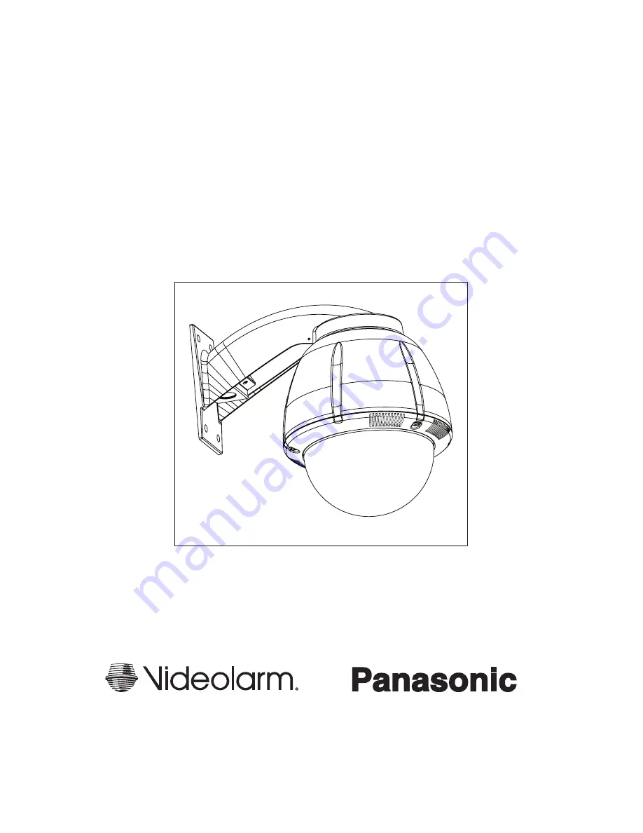
Outdoor Dome Housings
PODV7CWNS/PODV7CPNS
®
Manufactured By:
81-IN3090
01/18/07
Page 1: ...for Before attempting to connect or operate this product please read these instructions completely Installation Instructions Outdoor Dome Housings PODV7CWNS PODV7CPNS Manufactured By 81 IN3090 01 18 07 ...
Page 2: ...f the installation is intact Failure to comply with the foregoing could result in the unit separating from the support structure and falling with resultant damages or injury to anyone or anything struck by the falling unit UNPACKING Unpackcarefully Electroniccomponentscanbedamaged ifimproperlyhandledordropped Ifanitemappearstohave been damaged in shipment replace it properly in its carton and noti...
Page 3: ...ely mounted to a supporting structure capable of rigidly holding the weight of the entire unit GENERAL INSTRUCTIONS Tools Required 100 Flat Head Screwdriver Phillips Head Screwdriver PODV7CWNS PODV7CPNS IP Ready Network Housing IP Ready Network Housing with 24Vac input wall mount or pendant mounting heater blowers WV NS202 and camera ASSEMBLING THE UNIT 1 Remove content from all boxes Contents sho...
Page 4: ...tar washers provided in the packet assembly 1 Twist camera to secure Attach the Camera to the quick release plate Attach safety lanyard to the back of the camera Position the camera as shown below on the quick release plate and twist clockwise Please see Pansonic Operation Manual for additonal details 2 Complete wiring connections Connect the RJ45 network cable to into the network input Complete p...
Page 5: ... from the 2nd position to the 4th position of the terminal block Be careful not to short between the yellow and green wires 22 250 120 89 65 44 35 29 25 31 19 17 16 14 13 12 20 400 180 141 90 70 56 47 40 34 31 28 25 23 21 20 18 18 600 300 225 130 112 90 75 64 55 50 45 41 37 34 32 30 16 960 480 358 225 179 143 119 102 85 79 71 65 59 55 51 47 14 800 571 350 285 228 190 163 140 126 114 103 95 87 81 7...
Page 6: ... wall mount bracket 2 Attach the housing coupling Add thread sealing tape NOTE Pipe threads should be clean and rust free Use the Teflon tape included with the housing on the threads Teflon Tape A small roll of Teflon tape is provided with all pendant units 3 Mount the housing assembly to the mounting bracket and housing coupling A safety cable is included with the housing to temporarily hold it w...
Page 7: ...T use a strong solvent or cleanser Access panel Remove dome by twisting counterclockwise until it stops then pull down 2 To attach trim ring align pins with keyhole slots and turn clockwise about 12mm Secure 3 screw or use 3 security screws and security tool provided INSTALLING WALL MOUNT A wall mount bracket comes standard with this unit and a template is included to use as a guide for mounting t...
Page 8: ... Exploded View for Replacement Parts 16 18 1 1 2 3 1 19 11 10 6 5 4 7 8 9 2 3 12 1 13 14 15 17 ...
Page 9: ...PFD040 Upper Bracket Assembly 9 RPRH709 Housing Top 10 RPFD2612 Housing Top Gasket 11 WM10 Wall Mount Bracket Black 12 RPFD080 12VDC Blower Used on 24VAC Units 13 RPNET02 24 to 12DC Power Supply 14 RP FDJV 2000 Power Supply Bracket 15 RPPKPODV 1 spacers set of 4 16 SD0160 Pendent Mount Bracket 17 SD0170 Pendent Housing Coupling 18 RPPKE1125 Electrical Connector Packet 19 RPPKH2100 Housing Hardware...
Page 10: ... 10 2 000 3 250 R 733 2 132 2 981 1 537 5 500 Mounting Template ...