background image

– 75 –

Chapter 9 Other Useful Functions — Assigning functions to the USER buttons

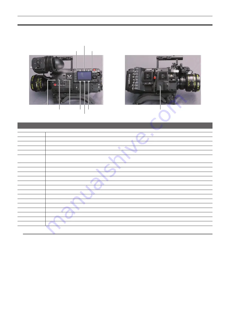
Assigning functions to the USER buttons

Selected functions can be assigned to the USER buttons <1> to <4> and the control panel operation buttons.
Set each function to be assigned to [USER1] to [USER10] in [MENU] 

 [SYSTEM SETTINGS] 

 [USER SWITCHS].

There are no functions assigned to the USER button in the factory settings.

USER2

USER5

USER6

USER8 USER10

USER1

USER3

USER4

USER7

USER9

Selectable functions

Item

Description

[INHIBIT]

Disables assignment of functions.

[SIX BUTTONS]

Sets against the USER <1> to <4> buttons, when the control panel operation button is used as the USER button.

[AWB]

Assigns the automatic white balance function.

[ABB]

Assigns the automatic black balance function.

[Y GET]

Assigns the function for displaying the luminance level of the image at the position indicated by the square marker displayed near the 

center.

[EXPAND]

Assigns the enlargement function.

[ASSIST]

Turns the advanced assist function on/off.

[WFM]

Enables/disables the viewfinder wave form display.

[BARS]

Assigns the color bars display function.

[FRAME LINE]

Displays/hides the frame line display function.

[VF COLOR]

Switches the viewfinder display to either monochrome or color display.

[MON1 COLOR]

Switches output images from the <MON OUT1> terminal.

[MON2 COLOR]

Switches output images from the <MON OUT2> terminal.

[SMOOTH MODE]

Assigns the smooth mode function.

[TEXT MEMO]

Assigns the text memo function.

[SHOT MARK]

Assigns the shot mark function.

[MAIN SLOT SEL]

Assigns the function for switching the card for recording when two or more cards are inserted in the main slot.

[SUB SLOT SEL]

Assigns the function for switching the card for recording when two or more cards are inserted in the sub slot.

[REC SW]

Assigns the function of the <REC> button.

@

@

NOTE


t

Only the following functions can be assigned to [USER5] to [USER10].
[INHIBIT], [EXPAND], [ASSIST], [FRAME LINE], [VF COLOR], [MON1 COLOR], [MON2 COLOR],[SMOOTH MODE]

Summary of Contents for Vericam 35

Page 1: ...35 Operating Guide W1014HM0 YI VQT5K88A E ...

Page 2: ... AVC Video that was obtained from a video provider licensed to provide the video Visit the MPEG LA LLC website http www mpegla com for details f f Use of DCF Technologies under license from Multi Format Inc How to read this document r r Illustrations f f Screenshots or illustrations may differ from the actual product r r Conventions used in this manual f f Words and phrases in brackets indicate de...

Page 3: ... 38 How to handle data recorded on P2 cards 39 Formatting a P2 card 40 Special recording functions 41 Hot swap recording 41 Shot mark recording function 41 Text memo recording function 41 Chapter 5 Control Panel 42 Control panel operation 43 Camera status display 43 Using the control panel extension unit 44 HOME screen 46 PLAY screen 48 TC screen 49 INFO screen 50 VIEW screen 51 MENU screen 52 Cha...

Page 4: ...11 Maintenance and Inspection 105 Inspections before shooting 106 Maintenance 107 Charging the built in battery 107 Warning system 108 Cases indicated by error codes 108 Cases indicated by error messages 108 Updating the camera firmware 111 Updating the firmware 111 Cleaning and storing 112 Cleaning the camera recorder 112 Cautions when storing the camera recorder 112 Chapter 12 Specification 113 ...

Page 5: ...Before using the camera read this chapter Chapter 1 Overview ...

Page 6: ...ts on the battery terminal Also if you drop the battery by mistake make sure that the battery body and the terminal are not warped Inserting a deformed battery into the camera recorder or attaching it to the battery charger may cause damages on the camera recorder or battery charger r r Cautions when throwing memory cards away or transferring them to others Formatting memory cards or deleting data...

Page 7: ...of these software 2 This product includes software licensed under MIT License 3 This product includes software developed by the OpenSSL Project for use in the OpenSSL Toolkit http www openssl org 4 This product includes software licensed under OpenBSD License 5 This product includes PHP freely available from http www php net 6 This software is based in part on the work of the Independent JPEG Grou...

Page 8: ...onic HD color viewfinder f f Connecting cable f f Slider unit f f Slider unit mounting screw 2 pcs f f Eye cup already attached to the Electronic HD color viewfinder f f Eye piece filter already attached to the Electronic HD color viewfinder Shoulder mount module f f Slide rail already attached to the shoulder mount module NOTE t t After unpacking the product dispose of the packing material proper...

Page 9: ...G P2 card page 36 SD memory card 3 P2 memory card 3 microP2 memory card 3 Visit the support desk at the website 3 P2 card page 36 1 The camera module and recording module are both required in this system The system will not run with only one of those modules 2 A battery holder is provided as standard on the recording module 3 Refer to our support desk at the following website for the latest inform...

Page 10: ...This chapter describes the names functions and operations of parts on the camera Chapter 2 Description of Parts ...

Page 11: ...p in red during recording 5 SHUTTER switch Switch for changing the electronic shutter 6 EI switch Switch for changing the EXPOSURE INDEX gain 7 Accessory mounting holes For attaching accessories f f Mounting hole size 3 8 16 UNC 8 Handle 9 LOCK switch Disables the operation of the camera module buttons and switches except the REC button Keep this in the LOCK position to prevent incorrect operation...

Page 12: ...his terminal prepare a double shielded cable equivalent to 5C FB 9 DC OUT terminal This is the DC12 V output terminal It provides a maximum current of 1 A 10 MIC IN terminal Terminal for connecting a microphone 11 LENS terminal Terminal for connecting a lens cable For details refer to the Operating Instructions for the lens Front 1 2 3 4 5 6 1 Accessory mounting holes For attaching accessories f f...

Page 13: ...le for control panel mounting part 3 Microphone holder mounting position 4 GPS module position This part has a built in GPS module Do not cover this part with metallic objects when the GPS is in use 5 Accessory mounting holes For attaching accessories f f Mounting hole size 1 4 20 UNC 3 8 16 UNC Bottom 1 1 Shoulder mount module tripod mounting holes For attaching the shoulder mount module or a tri...

Page 14: ... the setting menu or control panel operation is displayed 12 POWER switch Switch on off the power Even when the POWER switch is set to the OFF position the camera is not shut off from the main power 13 Jog dial button Used for setting moving items and selecting menus on the control panel 14 LOCK switch Disables the operation of the control panel buttons and switches except the REC button Keep this...

Page 15: ...ode on the camera For the cable to connect to this terminal prepare a double shielded cable equivalent to 5C FB 5 GENLOCK IN terminal Inputs reference signals when setting the genlock on the camera unit or when externally locking the time code The input signal is 3G HD SDI For the cable to connect to this terminal prepare a double shielded cable equivalent to 5C FB 6 MON OUT1 MON OUT2 terminal 3G ...

Page 16: ...or the microphone 6 LINE MIC switch Switch for switching audio input signals connected to the AUDIO IN 1 AUDIO IN 2 terminal LINE Select when audio equipment is connected by the line input MIC Select when a microphone is connected 7 PHONES terminal Connecting terminal of headphones for audio monitor Stereo mini jack 8 DC OUT RS terminal Terminal for DC 12 V output and REC trigger input The DC outp...

Page 17: ...ts Recording module Bottom 1 1 Shoulder mount module tripod mounting holes For attaching the shoulder mount module or a tripod f f Mounting hole size 1 4 20 UNC screw length 5 5 mm or shorter 3 8 16 UNC screw length 5 5 mm or shorter ...

Page 18: ...the focus When the display is enlarged some parts of the video may be hidden 6 Visibility adjustment ring Ring which adjusts the visibility Turn this ring while pressing and holding the upper button 7 Eye cup Front 1 2 1 Tally LED Lights up in red during recording This can be disabled in the viewfinder menu 2 Connection terminal Terminal for connecting the supplied cable This connects to the camer...

Page 19: ...lor viewfinder 4 Stopper Used when removing the viewfinder from the slider unit Top 1 2 1 Lock lever left right position Adjusts the position of the viewfinder left right 2 Lock lever front back position Adjusts the position of the viewfinder front back ...

Page 20: ...shorter 3 Stopper Pressed when removing the slide rail from the shoulder mount module Right side 2 1 3 1 Support rod lock knob Secures the rod in place Release Lock 2 Accessory attachment rosette Attach accessories such as hand grip f f Mounting screw size M6 screw length 9 mm or shorter 3 Slide rail lock knob Secures the slide rail in place Front 1 1 Support rod mounting holes Holes for connectin...

Page 21: ...Before you use the camera assemble the unit following the procedures in this chapter The mounting of accessories is also described in this chapter Chapter 3 Preparation ...

Page 22: ...ease lever of the camera module to raise the V edge Fig 4 t t Do not touch the mechanical parts near the V edge The V edge will move quickly which may cause injury Disassembling Fig 1 Fig 2 1 Push down the recording module release lever Fig 2 while pulling up the lock knob red of the recording module release lever Fig 1 The rear part of the recording module will slightly come up It will be difficu...

Page 23: ...ider unit Fig 2 Release the viewfinder lock lever by pushing it forward 3 Push down the lock lever backwards to lock 4 Connect the supplied connecting cable to the viewfinder connection terminal and the camera module s VF terminal Connect by aligning the red mark on the connector Disassembling a a Stopper 1 Remove the connecting cable 2 Push down the lock lever towards the front to release the loc...

Page 24: ...ve in the shoulder mount module from the rear until it clicks Fig 3 Before mounting confirm that the slide rail lock knob is released 5 After adjusting the slide position of the camera considering its weight balance lock by turning the slide rail lock knob clockwise Confirm that the camera is securely locked The camera may fall causing a malfunction or injury when the camera is off balance or the ...

Page 25: ...TE t t Select an appropriate hole in the adaptor taking into account the center of gravity of the camera and tripod adaptor combined Also make sure that the diameter of the selected hole matches the diameter of the pan head screw Removing the camera from the tripod adaptor While holding the red lever down move the black lever in the direction of the arrow and slide the camera backward to remove it...

Page 26: ...apter 3 Preparation Attaching and removing accessories Attaching the rain cover The figure below shows an example of use of the rain cover SHAN RC700 optional Tighten the cord Secure with the surface fastener ...

Page 27: ...and setting battery Using Anton Bauer batteries Anton Bauer batteries Release lever 1 Mount the Anton Bauer battery 2 Insert the battery terminal and slide in the direction of the arrow 3 Set the battery type From MENU SYSTEM SETTINGS BATTERY BATTERY SELECT select the battery type For details refer to Setting menu basic operations page 83 NOTE t t To remove the battery keep the release lever of th...

Page 28: ...wer of the camera is turned on such as lenses For the DC cable use a dual core shielded wire of AWG16 nominal cross section area 1 309 mm2 or thicker f f Make sure of the pin alignment of the DC output terminal of the external DC power supply and the camera DC IN terminal and connect the polarity correctly If the 12 V power supply is mistakenly connected to the GND terminal it may cause fire or ma...

Page 29: ... attached to the lens secure the cable through the cable clamp and connect it to the LENS terminal Fig 4 NOTE t t For handling the lens refer to the lens operating instructions t t When the lens is removed install the mount cap to protect the device Flange lens back adjustment The camera is equipped with the adjustment function of the flange back distance from the lens mounting surface to the imag...

Page 30: ...t stop Connection example Cable connector HR10A 7R 4SC 73 Hirose Electric Co Recording 1 GND 2 TALLY OUT Open collector output on the camera side Tally lamp on Low impedance Tally lamp off High impedance 3 Recording start stop switch This is connected in parallel to the REC button on the camera or the VTR button on the lens 4 12 V NOTE t t Make sure that polarity is correct before connecting an ex...

Page 31: ...y 05 00 New York 06 00 Dakar 05 30 06 30 Yangon 06 00 Chicago 07 00 Bangkok 06 30 07 30 07 00 Denver 08 00 Beijing 07 30 08 30 08 00 Los Angeles 09 00 Tokyo 08 30 09 30 Darwin 09 00 Alaska 10 00 Guam 09 30 Marquesas Islands 10 30 Lord Howe Island 10 00 Hawaii 11 00 Solomon Islands 10 30 11 30 Norfolk Island 11 00 Midway Islands 12 00 New Zealand 11 30 12 45 Chatham Islands 12 00 Kwajalein Atoll 13...

Page 32: ...This chapter describes the video combinations that can be recorded and the color grading in camera color grading that can be performed using the camera Chapter 4 Video Recording and Color Grading ...

Page 33: ...hen the 4K format or the variable frame rate function is enabled f f P2 memory cards of 2 GB cannot be used f f R A and E series P2 memory cards cannot be used for 1080 59 94P and 1080 50P r r Sub recorder Card slot microP2 memory card slot 2 Compatible memory cards microP2 memory card f f Proxy data can be recorded simultaneously in the sub recorder with some restrictions f f Videos with a variab...

Page 34: ... CODEC FREQUENCY VFR maximum frame rate SUB CODEC PROXY 4096 2160 AVC Intra4K 422 23 98p 60fps AVC Intra2K 422 G3 5 1024 540 25 00p 50fps 29 97p 60fps 50 00p 50fps AVC Intra2K 422 59 94p 60fps 3840 2160 AVC Intra4K 422 23 98p 60fps AVC Intra100 AVC LongG50 AVC LongG25 G3 5 960 540 25 00p 50fps 29 97p 60fps 50 00p 50fps AVC Intra100 AVC LongG25 59 94p 60fps 1920 1080 AVC Intra100 23 98p 60fps AVC I...

Page 35: ... The file extension is cdl 3D LUT f f Controlled in a 17 grid 3D LUT file f f Uploads data within the camera through an SD memory card f f Control parameters are saved to a file and stored in a P2 card together with videos etc f f The file extension is vlt Control combinations through settings MAIN COLOR Grading SEL SUB COLOR 3D LUT CDL Output Picture Adjustment MON 1 MON 2 EVF V Log ON V Log OFF ...

Page 36: ... a P2 card is inserted later that P2 card will not be accessed until the previously inserted P2 card has been recorded to f f Example When expressP2 memory cards are inserted in two slots If expressP2 memory cards are inserted into the two slots the cards are used as expressP2 memory cards in the order of the slot number 1 2 However if you remove the expressP2 memory card from slot 1 and then inse...

Page 37: ... on the viewfinder screen displays Turn off the power and then back on again and reformat the P2 card t t If a P2 card is inserted into another slot during playback the inserted card is not recognized and the card access LED does not light up The P2 card will start to be recognized when playback ends t t Even if a P2 card is inserted in a vacant card slot during recording the P2 card may not be re...

Page 38: ... 00p 29 97p Approx 64 min AVC Intra100 25 00p 29 97p Approx 64 min AVC LongG50 25 00p 29 97p Approx 128 min AVC LongG25 25 00p 29 97p Approx 256 min NOTE t t Indicated capacities include management and other area so the space available for recording is less than the values in the table above Dividing clips recorded on P2 cards If a P2 card with a capacity of 8 GB or more are used with the camera r...

Page 39: ...ry card is encrypted When it is not necessary any more format the SD memory card etc for security risk management Setting CPS password using the menu of the camera 1 Open the thumbnail screen and select SET from MENU SYSTEM SETTINGS CARDS MEDIA CPS PASSWORD The software keyboard to enter the CPS password is displayed 2 Enter the CPS password with the keyboard Enter PASSWORD and RETRY PASSWORD for ...

Page 40: ...below to use general IT tools such as Microsoft Windows Explorer or Apple Finder to transfer the data to a computer Be sure to use P2 Viewer Plus to write data back to a P2 card Transfer the corresponding CONTENTS folder and LASTCLIP TXT file together as a set Do not transfer individual files from the CONTENTS folder When copying copy the LASTCLIP TXT file at the same time as the CONTENTS folder W...

Page 41: ...g shot marks 1 From MENU SYSTEM SETTINGS USER SWITCHS set SHOT MARK for any setting from USER1 to USER4 2 During recording or while a clip is selected in the PLAY screen press the button to which the shot mark is assigned f f MARK ON is displayed and the short mark is added to the recorded clip f f Another press of the button displays MARK OFF and the shot mark disappears NOTE t t To add shot mark...

Page 42: ...This chapter describes how to change each setting and check the setting status using the control panel Chapter 5 Control Panel ...

Page 43: ...ed Bottom Sub slot recording status display f f REC Currently recording 2 Media free space display Top Main slot media remaining capacity display Bottom Sub slot media remaining capacity display f f min Remaining capacity 0 to 599 minutes f f h Remaining capacity more than 10 hours f f END No remaining free space f f WP Write protected f f OFF When SUB CODEC is OFF 3 Codec display Top Main slot co...

Page 44: ... f TCG 12 59 59 20 Displays the time code generator value f f TCR 12 59 59 20 Displays the time code reader value f f UBG AB CD EF 98 Displays the user bits generator value f f UBR AB CD EF 98 Indicates the user bits reader value f f Dur 00 59 59 23 Displays the duration 8 Lock display Displayed when button operations are disabled due to the LOCK switch Using the control panel extension unit The c...

Page 45: ...emoved control panel can be secured using the control panel mounting part Fig 1 Fig 3 Fig 2 1 Mount the control panel mounting part Fig 1 2 Mount the control panel onto the control panel mounting part Fig 2 3 Secure the control panel using screws Fig 3 NOTE t t Use the cable clamp to prevent the cable from getting snagged ...

Page 46: ...etting method WB Sets the color temperature white balance AWB Executes automatic white balancing PRESET Mode for selecting preset white balance values Up to 12 can be registered Presets can be added deleted using ADD DEL If AWB is performed the results are automatically added to the choices TEMP SHIFT Mode for making adjustments from the overall variable range GMg Shifts to the Green Magenta axis ...

Page 47: ...ODEC MAIN Restarting the system may be necessary if basic system settings are changed After confirming the three settings restart in accordance with the guide SUB CODEC Sets the sub recorder s codec AUDIO Sets the audio input and recording VR Sets the input volume IN Sets input channel switching and level control OUT Sets the output to a speaker or headphone ...

Page 48: ...ay Playback is paused by pressing the jog dial button Fast forward cue is performed by turning the jog dial button during playback SLOT Switches between the main recorder and sub recorder Displays the selected recorder on the upper left M Main recorder S Sub recorder DELETE Deletes selected clips COPY Copies selected clips SORT Sets the conditions for displaying clips in a list REPAIR Selects and ...

Page 49: ...Switches between the HOME screen and status display TC Time code UB User bits Dur Duration FREE REC RUN Switches between free run and recording run This is fixed to recording run when the variable frame rate function is enabled DF NDF Switches between drop frame and non drop frame SET Sets the time code generator ...

Page 50: ...rmware PERIPHERAL Displays information about peripheral devices USB network etc HISTORY Performs operations related to services Online Enters the support mode using PASS P2 Asset Support System TRACE LOG Writes the trace log to an SD memory card CARDS Performs operations related to recording media such as formatting etc AUTHENTICATE Moves to the screen for performing CPS card authentication system...

Page 51: ... 51 Chapter 5 Control Panel VIEW screen VIEW screen Displays video For status display contents configure MENU ...

Page 52: ...pter 5 Control Panel MENU screen MENU screen Displays the MENU Depending on the MENU SYSTEM SETTINGS MON OUT MENU DISP setting MENU is displayed for the output from the MON OUT1 terminal and MON OUT2 terminal ...

Page 53: ...This chapter describes how to prepare and adjust audio recorded at the time of shooting Chapter 6 Audio recording ...

Page 54: ... 2 Attach the microphone and tighten the clamping screw a Fig 2 Mount with the UP indication on the microphone facing up 3 Loosen the lock lever b adjust the angle of the microphone and tighten the lock lever Fig 3 4 Connect the microphone cable to the MIC IN terminal on the camera module Fig 4 5 According to the audio channel to be recorded select FRONT in control panel audio input Setting the au...

Page 55: ...select REAR in control panel audio input 3 Switch the LINE MIC switch on the AUDIO IN 1 terminal or AUDIO IN 2 terminal to LINE Setting the control panel 1 Press the HOME button to display the HOME screen 2 From SYSTEM AUDIO VR IN OUT select IN 3 Select REAR in CH1 2 IN CH3 4 IN is automatically set to FRONT NOTE t t When the input signal is digital audio AES EBU format set MENU SYSTEM SETTINGS AU...

Page 56: ...ut straight as SDI signal The details regarding audio is set in MENU SYSTEM SETTINGS AUDIO INPUT AUDIO LEVEL and AUDIO OUTPUT Adjusting the recording levels The camera performs manual adjustment and automatic adjustment of recording levels Automatic adjustment The recording levels in audio channel 1 2 can be automatically adjusted When audio channels 1 2 are set to FRONT audio channels 3 4 can be ...

Page 57: ...e maximum level so that the display does not reach 0 dB r r Recording standard level In MENU SYSTEM SETTINGS AUDIO LEVEL HEADROOM 18dB or 20dB can be selected Common settings for channels 1 through 4 NOTE t t When the level adjustment is set to MANUAL set whether to enable FRONT1 LIMITER FRONT2 LIMITER REAR1 LIMITER REAR2 LIMITER in MENU SYSTEM SETTING SYSTEM MODE AUDIO LEVEL This is set to OFF in...

Page 58: ...This chapter describes the viewfinder screen display and how to make adjustments Chapter 7 Viewfinder ...

Page 59: ...the viewfinder from side to side Adjust to a comfortable position 3 Lock the lock lever left right position r r Front back position adjustment 1 Loosen the lock lever front rear positions 2 Slide the viewfinder back and forth Adjust to a comfortable position 3 Lock the lock lever front back position r r Visibility adjustment 1 Turn the visibility adjustment ring while pressing holding the upper bu...

Page 60: ...NU button Screen adjustment items are displayed on the upper part of the screen 2 Turn the jog dial button to select the items you want to adjust 3 Press the jog dial button 4 Turn the jog dial button to make adjustments 5 Press the jog dial button 6 Press the EVF MENU button The screen adjustment items display disappears This can also be done in EVF MENU DISPLAY SETUP Direct camera settings The f...

Page 61: ...is released B W Switches to monochrome mode ON Display will be all black and white OFF Disables the monochrome mode SCAN Reverses the display NORMAL REVERSE r r USER SW 1 USER SW 2 Selects the function assigned to the EVF USER 1 EVF USER 2 button The settings configured here are applied to the settings in the camera s MENU VF SDI SETTINGS mutually excluding FALSE COLOR Description of settings MARK...

Page 62: ... are displayed in black and white Display patterns Color Level Description Type 1 Type 2 Red 108 0 109 5 93 6 94 7 White level clip Yellow 98 0 100 0 90 6 93 5 Lower area of the white level clip Pink 42 0 44 0 50 0 51 7 One stopover color from neutral gray Green 28 0 32 0 37 8 41 8 18 gray neutral color Blue 3 8 4 5 3 8 4 5 Upper area of the black level clip Purple 0 3 7 0 3 7 White level clip ...

Page 63: ...Image level ON OFF SPOT 109 ZEBRA2 DETECT ZEBRA1 DETECT 0 Displaying the center marker The marker is displayed when a setting other than OFF is set in MENU VF SDI SETTINGS MARKER CENTER MARKER Displaying the safety zone marker Items selected in MENU VF SDI SETTINGS MARKER SAFETY MARKER are displayed The size of the safety zone marker can be changed in MENU VF SDI SETTINGS MARKER SAFETY AREA Displa...

Page 64: ... focus so that the contours of the subject you want to focus on turn red In MENU VF SDI SETTINGS ASSIST COLOR GREEN or WHITE can be selected NOTE t t Only the output video from the viewfinder screen and VF SDI terminal are displayed Focus square display Set MENU VF SDI SETTINGS ASSIST ADVANCED ASSIST SW to ON Set MENU VF SDI SETTINGS ASSIST FOCUS SQUARES SW to ON Adjust the focus so that the squar...

Page 65: ...This chapter describes video output Chapter 8 Output and Screen Display ...

Page 66: ... MAIN CODEC P to PsF 4K OUT TYPE Signal Format 23 98p 29 97p 4096 2160 AVC Intra4K 422 OFF SQUARE 4096 2160 P 4 2 2 1 5G 4 2 SAMPLE INT 4096 2160 P 4 2 2 3G 2 ON SQUARE 4096 2160 59 94P 4 2 2 3G 4 2 SAMPLE INT 4096 2160 59 94P 4 2 2 3G 4 59 94p 4096 2160 AVC Intra4K 422 SQUARE 4096 2160 59 94P 4 2 2 3G 4 2 SAMPLE INT 4096 2160 59 94P 4 2 2 3G 4 25 00p 4096 2160 AVC Intra4K 422 OFF SQUARE 4096 2160...

Page 67: ...0p 3840 2160 AVC Intra4K 422 SQUARE 3840 2160 50 00P 4 2 2 3G 4 2 SAMPLE INT 3840 2160 50 00P 4 2 2 3G 4 23 98p 29 97p 1920 1080 AVC Intra100 OFF P 1920 1080 P 4 2 2 1 5G 1 Psf 1920 1080 Psf 4 2 2 1 5G 1 ON 1920 1080 59 94P 4 2 2 3G 1 59 94p 1920 1080 AVC Intra100 OFF 1920 1080 59 94P 4 2 2 3G 1 ON 1920 1080 59 94P 4 2 2 3G 1 25 00p 1920 1080 AVC Intra100 OFF P 1920 1080 25 00P 4 2 2 1 5G 1 Psf 19...

Page 68: ...3 98p 29 97p 59 94p 4096 2160 AVC Intra4K 422 OFF 2048 1080 59 94P 4 2 2 3G ON 1920 1080 59 94i 4 2 2 1 5G 25 00p 50 00p 4096 2160 AVC Intra4K 422 OFF 2048 1080 50 00P 4 2 2 3G ON 1920 1080 50 00i 4 2 2 1 5G 23 98p 29 97p 59 94p 3840 2160 1920 1080 AVC Intra4K 422 AVC Intra100 OFF 1920 1080 59 94P 4 2 2 3G ON 1920 1080 59 94i 4 2 2 1 5G 25 00p 50 00p 3840 2160 1920 1080 AVC Intra4K 422 AVC Intra10...

Page 69: ...MON OUT2 terminal Output format list SYSTEM MODE MON OUT Output Format FREQUENCY PIXEL MAIN CODEC MON OUT2 SIGNAL SEL 1080p to 1080i Signal Format 23 98p 29 97p 59 94p 4096 2160 AVC Intra4K 422 MON OUT1 OFF 2048 1080 59 94P 4 2 2 3G ON 1920 1080 59 94i 4 2 2 1 5G VF 1920 1080 59 94P 4 2 2 3G 25 00p 50 00p 4096 2160 AVC Intra4K 422 MON OUT1 OFF 2048 1080 50 00P 4 2 2 3G ON 1920 1080 50 00i 4 2 2 1 ...

Page 70: ...function in MENU VF SDI SETTINGS SURROUND VIEW Sets the focus assist function in MENU VF SDI SETTINGS ASSIST The setting details of the status display and marker display are the same as the details for the viewfinder Output format list SYSTEM MODE VF SDI DISPLAY Output Format FREQUENCY VF SDI 1080p to 1080i Signal Format 23 98p 29 97p 59 94p OFF 1920 1080 59 94P 4 2 2 3G ON 1920 1080 59 94i 4 2 2 ...

Page 71: ...GPS 7STOP T11 0 PXY 1 14 16 18 15 2 4 3 5 6 7 8 10 11 12 13 9 20 21 23 17 19 22 24 1 System pixel 2 System frequency 3 Main recorder recording status 4 Main codec 5 Sub recorder recording status 6 Sub codec 7 Card remaining free space 8 Battery charge level 9 Time code 10 Warning 11 Proxy 12 Focus bar only output from VF SDI terminal 13 FPS 14 Shutter 15 EXPOSURE INDEX 16 White balance 17 Y GET 18...

Page 72: ... GPS 7STOP T11 0 PXY FULL 2 1 14 17 18 15 3 10 5 11 6 7 8 12 13 22 16 20 9 4 19 21 1 Card remaining free space 2 System pixel 3 System frequency 4 Battery charge level 5 Main recorder recording status 6 Main codec 7 Sub recorder recording status 8 Sub codec 9 Proxy 10 Time code 11 Recording mode to be supported 12 Iris 13 FPS 14 ND filter 15 Shutter 16 Y GET 17 EXPOSURE INDEX 18 White balance 19 F...

Page 73: ...This chapter describes other useful features such as function buttons etc Chapter 9 Other Useful Functions ...

Page 74: ...lock is maintained accurately based on the time received Greenwich mean time and the time zone f f If the date and time display is different from the local time the time zone setting may be incorrect Recheck the time zone settings NOTE t t If it cannot position even after waiting several minutes it means that the GPS signals are weak and difficult to receive t t Position in the open space with a c...

Page 75: ...e marker displayed near the center EXPAND Assigns the enlargement function ASSIST Turns the advanced assist function on off WFM Enables disables the viewfinder wave form display BARS Assigns the color bars display function FRAME LINE Displays hides the frame line display function VF COLOR Switches the viewfinder display to either monochrome or color display MON1 COLOR Switches output images from t...

Page 76: ...emory cards are a standard that was established in 2006 by the SD Association for large capacity memory cards that exceed 2 GB SDXC memory cards are a standard that was established in 2009 by the SD Association for large capacity memory cards that exceed 32 GB Removing SD memory cards After opening the slot cover and making sure that the busy lamp is not illuminated push the SD memory card further...

Page 77: ...ewfinder LCD monitor and on the image output from the VF SDI terminal etc f f The internal clock is used for measuring the free run time code while the power is off and as time and year month day data of the user bits It is also used as the reference for file generation times during clip recording which determine the sorting order of thumbnails and the order of playback f f It is also used to gene...

Page 78: ...code range 59 94P 29 97P 00 00 00 00 to 23 59 59 29 23 98P 00 00 00 00 to 23 59 59 23 50P 25P 00 00 00 00 to 23 59 59 24 NOTE t t If you exit the time code setting screen without pressing the jog dial button the set values will be disabled Time code function during battery replacement Even during battery replacement the backup mechanism functions allowing the time code generator to continue operat...

Page 79: ...lue as the value of the external time code is output to the counter display area Do not set to the recording mode for several seconds until the sync generator has stabilized Furthermore lock the time code to the TC IN OUT terminal signal f f If you execute the slave once even if there is no longer TC IN OUT terminal and GENLOCK IN terminal input the slave status is maintained However in the follow...

Page 80: ...amera TC IN OUT terminal SDI OUT1 terminal GENLOCK IN terminal NOTE t t Sets the TC IN OUT terminal to output or input in MENU REC SETTINGS TC TC IN OUT SEL t t By setting MENU REC SETTINGS TC TC OUT REF to RECORDING on both cameras the two cameras will be able to record with the same time code on the video at the same time Operating procedure 1 From MENU REC SETTINGS TC TC IN OUT SEL set TC OUT f...

Page 81: ...This chapter describes how to operate the camera menus the structure and details of the setting menu Chapter 10 Menu Operations ...

Page 82: ...ets the display content of the output video from the viewfinder and VF SDI terminal FILE Performs file related operations such as reading writing menu settings data from to an SD memory card and handling lens files and lens chromatic aberration correction CAC files This item will be available in future version upgrade PERIPHERAL Applies settings related to functions used in conjunction with periph...

Page 83: ...utton f f The next level of screen is displayed If there is another level press the jog dial button again to display it f f The current setting value of the item selected on the right is displayed 4 Turn the jog dial button to place the cursor on the desired item 5 Press the jog dial button The item is in the setting status If there are two items the setting value selection frame may be displayed ...

Page 84: ...Intra100 Pxy AVC LongG50 Pxy AVC LongG25 Pxy OFF f f Factory setting AVC Intra2K 422 COLOR SETTING MAIN Sets the colors of videos entire camera system recorded in the main recorder V Log V 709 3D LUT f f Factory setting V Log GRADING Sets whether to apply the grading process This only enabled when V Log is set in MAIN ON OFF f f Factory setting OFF SUB Sets the colors of videos entire camera syste...

Page 85: ... rear microphone connected to the AUDIO IN 2 terminal ON OFF f f Factory setting OFF REAR MIC LEVEL Sets the input level of the rear microphone connected to the AUDIO IN 1 and AUDIO IN 2 terminals 40dB 50dB 60dB f f Factory setting 60dB REAR LINE LEVEL Sets the line input level from the AUDIO IN 1 terminal and AUDIO IN 2 terminal 4dB 0dB 3dB f f Factory setting 4dB FRONT1 MIC LOWCUT Enables disabl...

Page 86: ...TOR SEL1 Sets the audio channel to be output from the PHONES terminal CH1 2 Outputs audio channel 1 2 CH3 4 Outputs audio channel 3 4 f f Factory setting CH1 2 MONITOR SEL2 Sets the audio format mono stereo mix to be output from the PHONES terminal When MONITOR SEL1 is set to CH1 2 MONO CH1 MONO CH2 STEREO CH1 2 MIX CH1 2 When MONITOR SEL1 is set to CH3 4 MONO CH3 MONO CH4 STEREO CH3 4 MIX CH3 4 f...

Page 87: ...erminal and MON OUT2 terminal LEVEL A Selects the LEVEL A method LEVEL B Selects the LEVEL B DL method f f Factory setting LEVEL B MON OUT2 SIGNAL SEL Sets the output from the MON OUT2 terminal VF Selects the same output as the VF SDI terminal MON OUT1 Selects the same output as the MON OUT1 terminal f f Factory setting VF MON OUT1 STATUS Sets whether to show the status display on the output from ...

Page 88: ...y setting ON CENTER MARKER Controls the center mark 1 large 2 Open center large 3 small 4 Open center small OFF Does not display f f Factory setting 1 SAFETY MARKER Selects the type of frame for the safety zone marker 1 Box 2 Corners OFF Does not display Factory setting OFF SAFETY AREA Sets the size of the safety zone marker 80 100 1 step fixed aspect ratio f f Factory setting 90 FRAME MARK Enable...

Page 89: ... normal unencrypted format or CPS ENCRYPT encrypted format Data deleted as a result of formatting cannot be restored Always check the data before formatting MEDIA END ALARM Sets whether to generate an alarm sound when there is no remaining free space in the expressP2 memory card or the microP2 memory card ON OFF f f Factory setting ON USER SWITCHS USER1 Sets the function to be assigned to the USER...

Page 90: ...n connecting a battery to the DC IN terminal Remaining charge level is detected from the voltage level f f Factory setting DC POWER SUPPLY FULL Volt Sets the voltage in the remaining charge level full display when the battery remaining charge level is detected from the voltage level 13 0V 17 0V 0 1 V step f f Factory setting 15 5V NEAR END Volt Sets the remaining charge level near end voltage when...

Page 91: ...elects the frame rate from preset frame rates maximum of 12 Registration is done from the control panel VARIABLE Selects the frame rate from all available frame rates f f Factory setting PRESET PRESET VALUE Selects a value from a maximum of 12 values set from the control panel f f Factory setting 24fps VARIABLE VALUE Selects the frame rate from all available frame rates Selectable values vary depe...

Page 92: ...y setting 0dB GAIN OFFSET SW Sets whether to perform fine adjustment of control when dB is selected ON OFF f f Factory setting OFF OFFSET LEVEL Sets the fine adjustment level 0 0dB 3 0dB 0 1 dB step f f Factory setting 0dB SHUTTER SW Enables disables the shutter function ON OFF f f Factory setting ON DISPLAY MODE Sets the shutter display unit sec Displays in time deg Displays at shutter open angle...

Page 93: ...sts the linear matrix 127 127 f f Factory setting 0 G B _P Adjusts the linear matrix 127 127 f f Factory setting 0 B R _N Adjusts the linear matrix 127 127 f f Factory setting 0 B R _P Adjusts the linear matrix 127 127 f f Factory setting 0 B G _N Adjusts the linear matrix 127 127 f f Factory setting 0 B G _P Adjusts the linear matrix 127 127 f f Factory setting 0 COLOR CORRECTION SW Enables disab...

Page 94: ... Factory setting 0 G Yl PHASE Corrects the hue between green and yellow 63 63 f f Factory setting 0 Yl SAT Corrects yellow color saturation 63 63 f f Factory setting 0 Yl PHASE Corrects the yellow hue 63 63 f f Factory setting 0 Yl R SAT Corrects the color saturation between yellow and red 63 63 f f Factory setting 0 Yl R PHASE Corrects the hue between yellow and red 63 63 f f Factory setting 0 SK...

Page 95: ...only when USER is selected in UB MODE This can be set by each digit from 00 to FF f f Factory setting 00 TC UB Dur Switches the time code display to the user bits and duration counter display TC UB Dur f f Factory setting TC FREE REC RUN Sets the operation mode to advance the built in time code generator FREE RUN Advances regardless of the operation mode REC RUN Advances when recording is in proce...

Page 96: ...00 1 step fixed aspect ratio f f Factory setting 90 FRAME MARK Enables disables frame marker ON OFF f f Factory setting OFF FRAME SIG Sets frame marker aspect ratio 1 33 1 1 44 1 1 56 1 1 78 1 1 85 1 2 35 1 f f Factory setting 2 35 1 FRAME LEVEL Sets the level of the outside of the frame marker 0 100 10 step f f Factory setting 100 MARKER CHAR LVL Sets the marker and character luminance 50 60 70 f...

Page 97: ...lter transmittance ON OFF f f Factory setting ON EXTENDER Displays hides the extender ON OFF f f Factory setting ON Y GET Displays hides brightness of Y GET ON OFF f f Factory setting ON TC Displays hides the time code user bits and duration counter displays TCG TCR TCG OFF f f Factory setting TCG TCR P2 CARD REMAIN Displays hides the display of the remaining recording free space of a P2 card ON O...

Page 98: ...actory setting OFF LINE SW Enables disables the effective area line mark display function ON OFF f f Factory setting ON LINE COLOR Sets the effective area line mark color BLACK WHITE f f Factory setting WHITE MASK SIGNAL Sets the microphone level for the surround signal OFF 75 50 25 f f Factory setting OFF VF SDI DISPLAY VF SDI 1080p to 1080i Sets whether to output 1080i signals from the VF SDI te...

Page 99: ...RADING l SUB l 3D LUT l CDL l MON 1 l l MON 2 l l EVF l l AUDIO INPUT AES EBU IN FRONT MIC POWER FRONT MIC LEVEL REAR IN1 MIC POWER REAR IN2 MIC POWER REAR IN1 MIC LEVEL REAR IN2 MIC LEVEL REAR IN LINE LEVEL FRONT1 MIC LOWCUT FRONT2 MIC LOWCUT REAR1 MIC LOWCUT REAR2 MIC LOWCUT CH IN SEL l TEST TONE AUDIO LEVEL FRONT1 LEVEL l FRONT2 LEVEL l REAR1 LEVEL l REAR2 LEVEL l FRONT1 VR l FRONT2 VR l REAR1 ...

Page 100: ...US ZOOM FILTER EXTENDER Y GET TC P2 CARD REMAIN BATTERY REMAIN PROXY GPS MON OUT MARKER MON OUT1 SW MON OUT2 SW LCD SW CENTER MARKER SAFETY MARKER SAFETY AREA FRAME MARK FRAME SIG FRAME LEVEL MARKER CHAR LVL USER BOX USER BOX WIDTH USER BOX HEIGHT USER BOX H POS USER BOX V POS GENLOCK GENLOCK MODE H PHASE COARSE H PHASE FINE INFORMATION OPERATION TIME l VERSION l UPDATE l ONLINE SUPPORT l TRACE LO...

Page 101: ...ETTING TIME ZONE DATE FORMAT INITIALIZE LOAD FACTORY DATA CAMERA SETTINGS Item Operation UI SW VF Enhanced Enhanced SW FPS VFR SW l FPS MODE l PRESET VALUE l l VARIABLE VALUE l l l WHITE AWB l MODE l PRESET VALUE l l l TEMP SHIFT l l l GMg l R GAIN B GAIN AWB OFFSET SHOCKLESS WHITE BLACK ABB M PED R PED G PED B PED ABB OFFSET FLARE SW R FLARE G FLARE B FLARE EI MODE l SETTING ISO l l l SETTING GAI...

Page 102: ... G B _N G B _P B R _N B R _P B G _N B G _P COLOR CORRECTION SW R SAT R PHASE R Mg SAT R Mg PHASE Mg SAT Mg PHASE Mg B SAT Mg B PHASE B SAT B PHASE B Cy SAT B Cy PHASE Cy SAT Cy PHASE Cy G SAT Cy G PHASE G SAT G PHASE G Yl SAT G Yl PHASE Yl SAT Yl PHASE Yl R SAT Yl R PHASE SKIN CORRECTION SKIN AREA SW SKIN AREA HUE SKIN AREA TONE EXT FUNC FOCUS DISP LENS SETTING A IRIS TYPE A IRIS LEVEL EFFECT A IR...

Page 103: ...DI SETTINGS Item Operation UI SW VF MARKER SW l CENTER MARKER l SAFETY MARKER l SAFETY AREA FRAME MARK l FRAME SIG FRAME LEVEL MARKER CHAR LVL USER BOX l USER BOX WIDTH USER BOX HEIGHT USER BOX H POS USER BOX V POS ZEBRA ZEBRA MASTER SW l ZEBRA2 SW ZEBRA1 DETECT ZEBRA2 DETECT INDICATOR MASTER SW SYSTEM PIXEL SYSTEM FREQ REC FORMAT FPS SHUTTER EI WHITE IRIS FOCUS ZOOM FILTER EXTENDER Y GET TC P2 CA...

Page 104: ...NCED ASSIST SW l l PEAKING SW FOCUS SQUARES SW EXPAND POS EXPAND VALUE EXPAND MODE l PEAKING COLOR MONO SW FOCUS BAR SW SURROUND VIEW VIEW SW l LINE SW l LINE COLOR MASK SIGNAL VF SDI DISPLAY VF SDI 1080p to 1080i SMOOTH MODE l l WFM l l PERIPHERAL Item Operation UI SW VF GPS l ...

Page 105: ...Inspect the various parts of the camera before shooting Maintenance of the camera or frequently asked questions are also described in this chapter Chapter 11 Maintenance and Inspection ...

Page 106: ...on the control panel If the remaining battery level is low replace the battery with adequately charged one 6 Check the media free space with the status display on the control panel 7 Press the REC button and check the following f f The main slot card access LED flashes in orange f f The REC button lights up in red f f No system warning is displayed with the status display on the control panel 8 Pr...

Page 107: ... ON BACK UP BATT EMPTY may be displayed on the viewfinder screen for approx 5 seconds In that case charging of the built in battery is complete by connecting an external DC power supply or a battery and leaving the camera turned off for approximately four hours Set the date and time after charging is complete If BACK UP BATT EMPTY is still displayed in the viewfinder screen after charging when the...

Page 108: ... of microP2 memory card has failed The microP2 memory card whose CPS authentication failed cannot be recorded or played back f f The current operation will continue BACKUP BATT EMPTY Displays any reduced voltage detected on the backup battery in the internal clock when the power is turned on f f The current operation will continue f f Charge the built in battery CARD ERROR slot number Displayed wh...

Page 109: ...REGULAR SIG Recording is temporary suspended due to correct recording not possible because of the disruption of input signal from the GENLOCK IN terminal The clip will be divided f f Warning lamp flashes four times per second during continuous recording f f The operation will pause f f Recording will resume when the signal returns to normal During thumbnail and menu operation Display Description B...

Page 110: ...problem with data in the file Create the file again USER CLIP NAME MODIFIED When adding a counter value to the clip name characters must be deleted For the counter addition setting the user clip name plus the counter value can only contain up to 100 bytes Characters in the clip name are automatically deleted when the total number of characters exceeds this limit WRITE PROTECTED The P2 card or SD m...

Page 111: ...ate the firmware an SD memory card is required Use the camera or P2 Viewer Plus to format the SD memory card Fig 1 1 Download the firmware from the website http pro av panasonic net 2 Save the downloaded firmware to an SD memory card 3 Insert the SD memory card containing the firmware into the SD memory card slot of the recording module 4 Turn the power on 5 Press the INFO button to display the IN...

Page 112: ...e there is heavy oil smoke or dust may lead to malfunctions due to rust on terminal connectors etc f f Do not let the battery terminal contact a metal object such as a necklace or hairpin Short circuit may occur between terminals and it may lead to heat generation Touching on a heated part may cause severe burns f f Store the battery with electrically discharged If you store it for a long period o...

Page 113: ...This chapter describes the specifications of this product Chapter 12 Specification ...

Page 114: ...nsumption 99 W with all optional accessories connected and maximum power supplied from each output terminal indicates safety information Ambient operating temperature 0 C 40 C 32 F 104 F Ambient operating humidity 10 85 relative humidity Storage temperature 20 C 60 C 4 F 140 F Weight Approx 5 0 k 11 02 lbs excluding accessories Dimensions W H D Body only 179 0 mm 230 5 mm 347 0 mm 7 1 16 inches 9 ...

Page 115: ... 94p 50p 29 97p 25p 23 98p 3840 2160 59 94p 50p 29 97p 25p 23 98p 1920 1080 59 94p 50p 29 97p 25p 23 98p Recording and playback time MAIN CODEC When using a 256 GB expressP2 memory card f f AVC Intra 4K 422 VFR ON 50p 59 94p Approx 36 min f f AVC Intra 4K 422 VFR OFF 24p Approx 90 min f f AVC Intra 100 VFR ON 50 fps 60 fps Approx 128 min Figures are for continuous recording as one clip Depending o...

Page 116: ...pin PHONES terminal Stereo mini jack Speaker 20 mm diameter round 1 Viewfinder Display panel OLED organic EL 0 7 type 2760000 dots Video input method 1080 59 94p 1080 50p 1080 60p Other input output GENLOCK IN terminal HD 1 5G 3G SDI 0 8 V p p 75 Ω TC IN OUT terminal BNC 1 Input output switching f f Input 0 5 V 8 V p p 10 kΩ f f Output 2 0 V 0 5 V p p low impedance DC IN terminal XLR 1 4 pin DC 12...

Page 117: ...rd 76 Frame marker 63 G GPS 74 H Headphones 57 Hot swap recording 41 I In camera grading 35 Internal clock 31 L Lens 29 Adjustment 29 Mounting 29 M Menu Setting menu 83 microP2 memory card 36 Inserting 36 Removing 37 Write protect 37 O Output format MON OUT1 output 68 MON OUT2 output 69 SDI output 66 VF SDI output 70 P P2 card 36 Formatting 40 Recording time 38 Status 37 Peaking display focus in r...

Page 118: ...Index 118 Z Zebra patterns 63 ...

Page 119: ...ut collection and recycling of old products and batteries please contact your local municipality your waste disposal service or the point of sale where you purchased the items Penalties may be applicable for incorrect disposal of this waste in accordance with national legislation For business users in the European Union If you wish to discard electrical and electronic equipment please contact your...

Reviews: