– 44 –
Chapter 5 Control Panel — Control panel operation
f
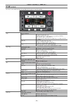
Channel display
[1]/[2] or [3]/[4]
f
Level meter display
Displays the level represented by 19 bars. (2 dB increments)
f
Standard level bar
At the
−
18 dB position or the
−
20 dB position
The standard is in [MENU]
→
[SYSTEM SETTINGS]
→
[AUDIO LEVEL]
→
[HEADROOM]
6 Warning/error displays
: Warning (details are displayed on the time code display in the following cases)
f
[SYSTEM ERROR !]
f
[TURN POWER OFF !]
f
[REC WARING !]
f
[CARD ERROR !] (when recording has stopped)
f
[LOW BATTERY !]
f
[MEDIA END !]
: Alert
7 Time code display
f
[TCG 12:59:59:20]: Displays the time code generator value.
f
[TCR 12:59:59:20]: Displays the time code reader value.
f
[UBG AB CD EF 98]: Displays the user bits generator value.
f
[UBR AB CD EF 98]: Indicates the user bits reader value.
f
[Dur.00:59:59:23]: Displays the duration.
8 Lock display
Displayed when button operations are disabled due to the <LOCK> switch.
Using the control panel extension unit
The control panel can still be used after it is removed. To remove the control panel, set the <POWER> button to <OFF>.
Fig. 1
Fig. 2
Fig. 3
1
Press the <RELEASE> switch while lifting up the control panel. (Fig. 1)
The control panel will come off.
2
Attach the control panel extension unit. (Fig. 2)
3
Connect the control panel extension unit cable to the control panel. (Fig. 3)
Summary of Contents for Vericam 35
Page 1: ...35 Operating Guide W1014HM0 YI VQT5K88A E ...
Page 5: ...Before using the camera read this chapter Chapter 1 Overview ...
Page 65: ...This chapter describes video output Chapter 8 Output and Screen Display ...
Page 113: ...This chapter describes the specifications of this product Chapter 12 Specification ...
Page 118: ...Index 118 Z Zebra patterns 63 ...


