1
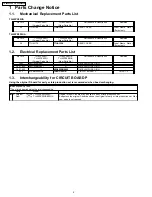
Parts Change Notice
2
1.1.
Mechanical Replacement Parts List
2
1.2.
Electrical Replacement Parts List
2
1.3.
Interchangeability for CIRCUIT BOARD P
2
2
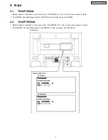
Note
3
2.1.
TH-42PX50UA
3
2.2.
TH-42PX500UA
3
3
Adjustment Procedure
4
3.1.
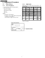
Driver Set-up
4
3.2.
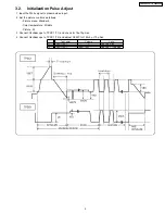
Initialization Pulse Adjust
5
3.3.
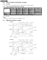
P.C.B. (Printed Circuit Board) exchange
6
3.4.
Adjustment Volume Location
6
3.5.
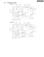
Test Point Location
7
4
Conductor Views
9
©
2005 Matsushita Electric Industrial Co., Ltd. All
rights
reserved.
Unauthorized
copying
and
distribution is a violation of law.
TH-42PX50UA
TH-42PX500UA
4.1.
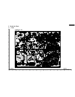
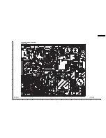
P-Board
9
5
Block and Schematic Diagrams
13
5.1.
Schematic Diagram Notes
13
5.2.
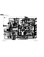
P-Board Block Diagram
14
5.3.
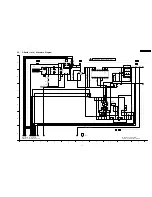
P-Board (1 of 6) Schematic Diagram
15
5.4.
P-Board (2 of 6) Schematic Diagram
16
5.5.
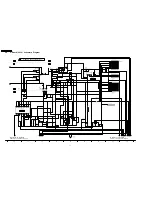
P-Board (3 of 6) Schematic Diagram
17
5.6.
P-Board (4 of 6) Schematic Diagram
18
5.7.
P-Board (5 of 6) Schematic Diagram
19
5.8.
P-Board (6 of 6) Schematic Diagram
20
6
Replacement Parts List (P-board)
21
6.1.
Replacement Parts List Notes
21
6.2.
Replacement Parts List (P-board)
22
7
Schematic Diagram for printing with A4
27
Digital High Definition Plasma Television
Subject :
Change P-board
Please file and use this manual together with the service manual for Model No
TH-42PX50U (Main), ORDER NO. ITD0503013CE
TH-42PX500U (Main), ORDER NO. MTNC050632C1
CONTENTS
Page
Page
ORDER NO. ITD0510061SE
B1
9
Canada : B07
Summary of Contents for TH-42PX500UA
Page 7: ...3 5 Test Point Location 7 TH 42PX50U TH 42PX500U ...
Page 8: ...8 TH 42PX50U TH 42PX500U ...
Page 12: ...TH 42PX50U TH 42PX500U 12 ...
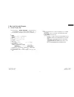
Page 13: ...5 Block and Schematic Diagrams 5 1 Schematic Diagram Notes TH 42PX50U TH 42PX500U 13 ...
Page 21: ...6 Replacement Parts List P board 6 1 Replacement Parts List Notes 21 TH 42PX50U TH 42PX500U ...


