


22
3. Remove the Stand brackets (L, R) fastening screws (
×
4
each) and the Stand brackets (L, R).
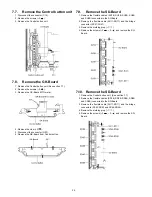
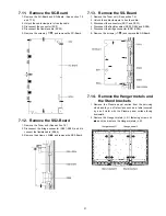
7.15. Remove the C1-Board
1. Remove the Control button unit. (See section 7.7.)
2. Remove the Hanger metal R and the Stand bracket R.
(See section 7.14.)
3. Remove the flexible cables holder fastening screws (
×
10
).
4. Disconnect the flexible cables (CB1, CB2, CB3, CB4 and
CB5).
5. Disconnect the flexible cable (C10).
6. Disconnect the connector (C14).
7. Remove the screws (
×
4
) and remove the C1-Board.
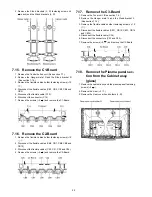
7.16. Remove the C2-Board
1. Remove the flexible cables holder fastening screws (
×
10
).
2. Disconnect the flexible cables (CB6, CB7, CB8, CB9 and
CB10).
3. Disconnect the flexible cables (C20, C21, C22 and C26).
4. Remove the screws (
×
4
) and remove the C2-Board.
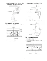
7.17. Remove the C3-Board
1. Remove the Tuner unit. (See section 7.4.)
2. Remove the Hanger metal L and the Stand bracket L.
(See section 7.14.)
3. Remove the flexible cables holder fastening screws (
×
10
).
4. Disconnect the flexible cables (CB11, CB12, CB13, CB14
and CB15).
5. Disconnect the flexible cable (C36).
6. Disconnect the connectors (C33 and C35).
7. Remove the screws (
×
5
) and remove the C3-Board.
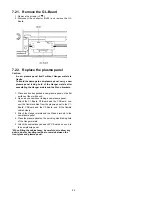
7.18. Remove the Plasma panel sec-
tion from the Cabinet assy
(glass)
1. Remove the cabinet assy and the plasma panel fastening
screws (
×
2 ).
2. Remove the claw (
×
2 ).
3. Remove the Rear cover hook holders (L, R).
Summary of Contents for TC-P54V10 - Viera 54" Full HD 1080p
Page 16: ...16 6 4 No Picture ...
Page 27: ...27 8 1 4 Adjustment Volume Location 8 1 5 Test Point Location ...
Page 29: ...29 ...
Page 30: ...30 ...
Page 36: ...36 ...
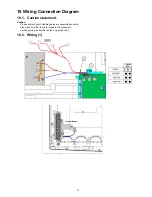
Page 38: ...38 10 3 Wiring 2 ...
Page 39: ...39 10 4 Wiring 3 ...
Page 40: ...40 10 5 Wiring 4 ...
Page 41: ...41 10 6 Wiring 5 ...
Page 42: ...42 ...
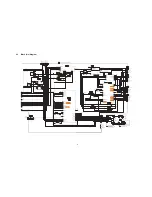
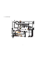
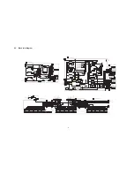
Page 43: ...43 11 Schematic Diagram 11 1 Schematic Diagram Note ...
Page 84: ...84 A B C D E F G H I 1 2 3 4 5 6 P P 1 BOARD COMPONENT SIDE ETX2MM761MGN ...
Page 98: ...98 ...
Page 100: ...100 13 1 2 Packing 1 ...
Page 101: ...101 13 1 3 Mechanical Replacement Parts List ...
Page 104: ...104 Safety Ref No Part No Part Name Description Q ty Remarks 47 XZB7 5X9D05 POLY BAG SCREW 1 ...
Page 105: ...105 13 2 Electrical Replacement Parts List 13 2 1 Replacement Parts List Notes ...