background image

5

3 Service Navigation

3.1.

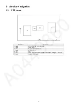
PCB Layout

Board Name

Main Device

A-Board

TUN, OFDM, ADV, LD4, STBY EEP

P-Board

Power Supply

GK-Board

Function SW for LGD panel

K-Board

LED, RM, CATS

FR-Board

GCX

HE-Board

HEVC    

( Non serviceable, HE-Board should be exchanged for service )

MD-Board

Human Activity Sensor

Summary of Contents for TC-58AX800U

Page 1: ... Panasonic Corporation 2014 Unauthorized copying and distribution is a violation of law ORDER NO MTNC140315CE 58 inch Class 4K Ultra HD TV Model No TC 58AX800U LA52 Chassis ...

Page 2: ...g timing chart 16 7 3 LCD Panel test mode FR test mode 16 8 Disassembly and Assembly Instructions 17 8 1 Disassembly Flow Chart for the Unit 17 8 2 Disassembly Procedure for the Unit 17 9 Measurements and Adjustments 36 9 1 Voltage chart of A Board 36 9 2 Voltage chart of P Board 36 9 3 Voltage chart of HE Board 36 9 4 Voltage chart of FR Board 36 10 Block Diagram 37 10 1 Main Block Diagram 37 10 ...

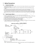
Page 3: ...units Replace the entire wiring unit instead 6 When conducting repairs and servicing do not twist the Fasten connectors but plug them straight in or unplug them straight out 1 2 Touch Current Check 1 Plug the AC cord directly into the AC outlet Do not use an isolation transformer for this check 2 Connect a measuring network for touch currents between each exposed metallic part on the set and a goo...

Page 4: ... of the assembly 3 Use only a grounded tip soldering iron to solder or unsolder ES devices 4 Use only an anti static solder removal device Some solder removal devices not classified as anti static ESD protected can generate electrical charge sufficient to damage ES devices 5 Do not use freon propelled chemicals These can generate electrical charges sufficient to damage ES devices 6 Do not remove a...

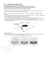
Page 5: ...ee solder has a higher melting point than standard solder Typically the melting point is 50 70 F 30 40 C higher Please use a high temperature soldering iron and set it to 700 20 F 370 10 C Pb free solder will tend to splash when heated too high about 1100 F or 600 C If you must use Pb solder please completely remove all of the Pb free solder on the pins or solder area before applying Pb solder If ...

Page 6: ...d Name Main Device A Board TUN OFDM ADV LD4 STBY EEP P Board Power Supply GK Board Function SW for LGD panel K Board LED RM CATS FR Board GCX HE Board HEVC Non serviceable HE Board should be exchanged for service MD Board Human Activity Sensor ...

Page 7: ...7 4 Specifications ...

Page 8: ... eMMC IC8903 5 1 2 Replacement of ICs When Main IC is replaced eMMC IC8903 should be also replaced with new one the same time When eMMC IC8903 is replaced Main IC is not necessary to be replaced the same time After the replacement of IC SELF CHECK should be done to generate the final KEY data How to SELF CHECK While pressing VOLUME button on the main unit press MENU button on the remote control fo...

Page 9: ...b items change in forward direction in reverse direction 6 1 3 How to exit Switch off the power with the POWER button on the main unit or the POWER button on the remote control 6 1 4 Contents of adjustment mode Value is shown as a hexadecimal number Preset value differs depending on models After entering the adjustment mode take note of the value in each item before starting adjustment Main item S...

Page 10: ...rrence after shipment will be cleared by Self check indication and forced to factory shipment setting 6 2 3 POWER ON TIME COUNT Note To display TIME COUNT menu highlight position then press MUTE for 3 sec Time Cumulative power on time indicated hour minute by decimal Count Number of ON times by decimal Note This indication will not be cleared by either of the self checks or any other command 6 2 4...

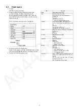
Page 11: ...ach time power is switched on Selection RF HDMI1 HDMI2 AV Off give priority to a last memory Channel Select channel when input signal is RF Set the channel each time power is switched on Selection Any channel number or means the channel when turns off Volume Adjust the volume when each time power is switched on Range 0 to 100 Vol Max Adjust maximum volume Range 0 to 100 OSD Ctrl Restrict the OSD S...

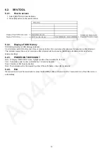
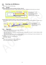
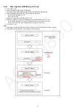
Page 12: ...then copy to other TVs 6 4 2 Preparation Make pwd file as startup file for a or b in a empty USB Memory 1 Insert a empty USB Memory to your PC 2 Right click a blank area in a USB Memory window point to New and then click text document A new file is created by default New Text Document txt 3 Right click the new text document that you just created and select rename and then change the name and exten...

Page 13: ...llowing password for a or b by using remote control a For Board replacement 2770 b For Hotel 4850 Data will be copied from TV set to USB Memory It takes around 2 to 6 minutes maximum for copying 4 After the completion of copying to USB Memory remove USB Memory from TV set 5 Turn off the TV set Note Following new folder will be created in USB Memory for data from TV set a For Board replacement user...

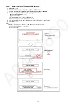
Page 14: ...ent 2771 b For Hotel 4851 Data will be copied from USB Memory to TV set 4 After the completion of copying to USB Memory remove USB Memory from TV set a For Board replacement Data will be deleted after copying Limited one copy b For Hotel Data will not be deleted and can be used for other TVs 5 Turn off the TV set Note 1 Depending on the failure of boards function of Data copy for board replacement...

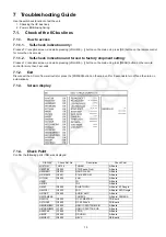
Page 15: ...or press the POWER button on the main unit for 3 seconds to turn off and then turn on automatically 7 1 3 Screen display 7 1 4 Check Point Confirm the following parts if NG was displayed DISPLAY Check Ref No Description Check Point H14TUN TU6706 TUNER A Board H90STBY IC8000 STM Peaks Pro4 A Board H92MEM1 IC8900 NAND FLASH A Board H91MEM2 IC8901 STM EEPROM A Board H17LAN IC8600 LAN A Board H96ID ID...

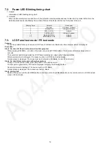
Page 16: ...ted by LCD Panel are displayed Judge by the following method Still abnormal picture is dislpayed The cause must be in LCD Panel Exit test mode Normal picture is displayed The cause must be in A Board or FR Board Go into FR test mode Step2 Go into FR test mode and confirm the symptom During in LCD Panel test mode press OK button on the remote control The test pattern generated by FR board is displa...

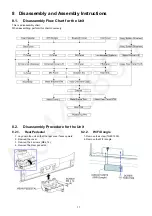
Page 17: ...rt When assembling perform this chart conversely 8 2 Disassembly Procedure for the Unit 8 2 1 Rear Pedestal 1 Lay down the unit so that the rear cover faces upward 2 Remove the cover 3 Remove the 4 screws M4 x 14 4 Remove the Rear pedestal 8 2 2 WiFi Dongle 1 Remove the screw THEC1509 2 Remove the WiFi dongle ...

Page 18: ...t cover L R 1 Remove the 4 screws THEC1509 2 Remove the Bottom ornament cover L and R 8 2 6 Back cover 1 Remove the screw XTV3 8GFJK 2 Remove the 4 M6 CAP 3 Remove the 31 screws THEC1509 4 Remove the Back cover 8 2 7 Circuit Units 1 Remove the 2 screw THEJ036J 2 Disconnect the USB Cable 3 Remove the Circuit units 8 2 8 Bluetooth Dongle 1 Remove the Bluetooth module ...

Page 19: ...anel 4 Remove the Barrier P PCB 8 2 11 A Panel 1 Remove the 3 screws THEJ036J 2 Remove the Side AV bracket 3 Remove the Bottom AV bracket 4 Disconnect the connectors A02 A10 A12 A20 A23 A40 A41 and A43 5 Disconnect the flexible cables A15 and A16 6 Remove the 5 screws THEJ036J 7 Remove the A Panel 8 2 12 GK Panel 1 Disconnect the connector GK4 2 Remove the Key button bracket ...

Page 20: ... 1 Disconnect the connector HE40 HE41 and HE42 2 Remove the 3 screws THEJ036J 3 Remove the HE Panel 8 2 15 Heat Sink FR Panel and HE Panel 1 Remove the 4 screws THEJ036J 2 Remove the Heat sink 8 2 16 Ornament Cover L R 1 Remove the 3 screws XTV3 8GFJK 2 Remove the 4 screws THEJ036J 3 Remove the Ornament cover L R 8 2 17 Assy Bottom Ornamet 1 Remove the 6 screws XYN4 F10FJ 2 Remove the Assy Bottom ...

Page 21: ...r SQ 1 Remove the 2 speakers SQ 8 2 21 Metal Bracket BTM 1 Remove the 6 screws THEJ024 2 Remove the Metal Bracket BTM 8 2 22 MD Panel 1 Remove the MD Panel 2 Disconnect the connector MD1 3 Remove the IR motion sensor 8 2 23 K Panel 1 Remove the K Panel 2 Disconnect the connector K10 3 Remove the LED panel 8 2 24 Assy Ornament Case 1 Remove the 2 screws THEJ036J 2 Remove the Assy Ornament Case ...

Page 22: ...ve the 4 screws THEC1509 2 Remove the Assy Rear panel T L and R 8 2 27 Cabinet 1 Remove the 12 screws THEC151J 2 Remove the Cabinet 8 2 28 Metal Frame TOP L 1 Remove the 10 screws THEJ036J 2 Remove the 4 Metal Frame TOP L 8 2 29 Metal Rear Panel BTM 1 Remove the 4 screws THEJ036J 2 Remove the Metal Rear Panel BTM ...

Page 23: ...2 30 Metal Frame L 1 Remove the 4 screws THEJ036J 2 Remove the 4 Metal Frame L 8 2 31 Heat Sink 1 remove the 17 screws THEJ036J 2 Remove the 2 Heat Sink 8 2 32 Positioning PIN 1 Remove the 2 positioning PIN ...

Page 24: ...24 8 2 33 EMI processing ...

Page 25: ...25 ...

Page 26: ...26 ...

Page 27: ...27 ...

Page 28: ...28 ...

Page 29: ...29 ...

Page 30: ...30 ...

Page 31: ...31 ...

Page 32: ...32 ...

Page 33: ...33 ...

Page 34: ...34 ...

Page 35: ...35 ...

Page 36: ...9 1 71V 1 89V FPGA2 5V TP1806 2 38V 2 63V DP3 3V TP1810 3 20V 3 50V DP1 2V TP1830 1 10V 1 28V HDMI1 1V TP1802 1 05V 1 19V VOLTAGE TEST POINT SPECIFICATION STEP 1 STEP 2 24V TP7407 1V 24 1 2V 16V TP7410 1V 16 0 8V 5VS TP7501 5 25 0 25V 5 25 0 25V PFC TP7201 or TP7202 340V 390 15V HOT VOLTAGE TEST POINT SPECIFICATION HEVC_1 1V TP6120 1 050V 1 150V HEVC_1 5V TP6122 1 425V 1 575V HEVC_3 3V TP6123 3 13...

Page 37: ... 3V USB1 SUB3 3V SLOT SPI FLASH DDR_I F ARC SW PANEL12V KEY FR3 3V DP3 3V FPGA1 0V_2 DCDC REMOTE_RECEIVER GK GCX3 3V Y PB PR BLUETOOTH LEVEL SHIFT SPI FLASH HDMI3 3V REG 5VS DCDC LVDS_DATA USB5V USB2 SUB5V FR 20 SWITCH REMOTE_IN WiFi STB5V ARC_OUT ETHERPHY DDR_I F RX1DDC SUB5V P2 REG DCDC IECIN FPGA1 8_2V A16 SUB3 3V SUB1 1V FR16 C A T S SENSOR I2C BUS REPEATER L DCDC SD CARD SPEAKER L Skype camer...

Page 38: ...9030 46 3 IC9600 8 IC7401 48 26 SYSTEM_BUS 1 2 5 FRC 2 1 1V BL_ON POWER_ON PHOTO COUPLER 3 6 BL_0N 4 LVDS RX 4 P5 IC7301 Q7301 Q7302 KEY 12V 2 7 4 BL_SOS 44 GCX3 3V 4 5 POWER_ON PWM_ENB SUB_ON SYSTEM_BUS KEY IC9504 SYSTEM_BUS POWER_ON PWM_ENB GCX1_COMMON BL_SOS PNL_3D_ON 1 IC7402 Q7408 09 Q7422 23 IC9050 20 BL_0N Q7202 2 50 27 BL_ON GCX1 1V 2 9 PFC BL_0N POWER BL_ON_INPUT GCX2_1 5V T CON DI VbyOne...

Page 39: ...C1809 IC3501 TX0 IC1807 HDMI I F TX1 RX3 20 DISPLAY PORT 27 IC1500 1 8V 1 DDR3 FPGA2 5V 2 5 17 3 5 FR3 3V LVDS TX IIC_0 4 5 VIXS_ALIVE TMDS DATA CLOCK IC1805 DDR_I F FLASH I F RX1DDC DDC_IIC_H IC1803 TX1 2 SPI DP HDMI RX0 2 5V 16V JK3502 IIC_0 FLASH I F 16V IIC_0 3 3V TX1 1 LEVEL SHIFT 2 LVDS RX 1 2V IC5400 1 IC1811 IC1550 IC1812 HEVC_XRST IC1551 HEVC_SPDIF 2 5V FPGA_XRST 6 3 3V HDMI1 1V IC6121 6 ...

Page 40: ...IC_5 CN0100 1 8V USB_I F JK8602 IIC_1 IC8200 OVP TV_TUNER SYSTEM_BUS IC8458 ETHERNET K10 CEC K SN2870 HDMI_5V_DET1 L R IN SOS 1 M08 IIC_1 C A T S SENSOR BL_ON_INPUT MD GCX_XRST 13 STB3 3V R_LED_ON 12 IC8100 IC8457 IC8000 IC8101 STB1 1V WOOFER 2 3 3V SD DATA 11 ETHER_I F TU6706 CH1 IC8901 HDMI_CEC COM IIC_0 HDMI_5V_DET0 A23 5 A20 7 SD CARD SLOT DDR_I F IC4900 POWER_ON DCDCEN 3 16 JK8650 DDR3 1 1V U...

Page 41: ...Diagram 11 1 Caution statement Caution Please confirm that all flexible cables are assembled correctly Also make sure that they are locked in the connectors Verify by giving the flexible cables a very slight pull 11 2 Wiring 1 ...

Page 42: ...42 11 3 Wiring 2 ...

Page 43: ...43 11 4 Wiring 3 ...

Page 44: ...44 11 5 Wiring 4 11 6 Wiring 5 ...

Reviews: