


Standby Operation
Standby Operation
20
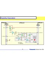
When the main power switch is activated, it is sensed on the A board by the MPU IC1100. The TV_SUB_ON
signal is subsequently issued in response on pin 8 of connector A4/AP4. It turns on the transistors Q7224 and Q7223 to
output the “Relay voltage on pin 15 of connector AP2/P2. The TV Sub_On signal is also provided to the relay via the
resistor R7208 and pin 17 of connector AP2/P2. This pulls the contacts of the AC relay on the P board. The AC input is
rectified and provided to the LCD panel for conversion into 24Vdc. The 24V is then provided to the inverter circuit of the
LCD panel to produce the 120Vac that powers the backlight CCFLTs. The same 24V passes through the P board and
enters the AP board for conversion into other voltages.
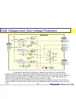
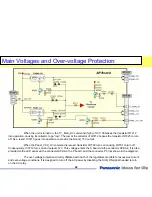
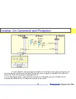
The over-voltage protection circuitry affiliated with each of the regulators located on the AP board monitors
for over-voltage conditions. It is designed to turn off the AC power by disabling the SUB_ON command that turns on the
AC relay.
When an over-voltage condition is detected on the AP board, the voltage at the base of transistor Q7207
goes “high” to turn on Q7207, Q7206, Q7205, and Q7204. The TV_SUB_ON voltage at pin 17 of connector A2/AP2 is now
grounded through Q7204 and the unit shuts down. To turn the unit back on, disconnect and reconnect the AC cord before
pressing the power button.
Summary of Contents for TC-32LX85 Operating Manual (English
Page 6: ...Purposely Left Blank Purposely left blank 6 ...
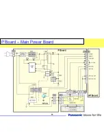
Page 15: ...P Board P Board Main Power Board Main Power Board 15 T801 D821 ...
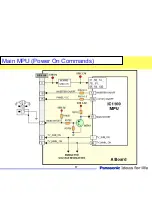
Page 17: ...Main MPU Power On Commands Main MPU Power On Commands 17 ...
Page 19: ...Standby Operation Standby Operation 19 ...
Page 24: ...Purposely Left Blank Purposely left blank ...
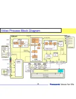
Page 25: ...Video Process Block Diagram Video Process Block Diagram 25 ...
Page 27: ...Audio Process Block Diagram Audio Process Block Diagram 27 ...
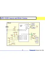
Page 29: ...MPU SOS Inputs and Blink Codes MPU SOS Inputs and Blink Codes 29 ...
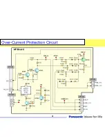
Page 31: ...Over Over Current Protection Circuit Current Protection Circuit 31 ...
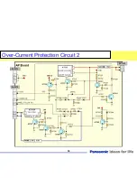
Page 33: ...Over Over Current Protection Circuit 2 Current Protection Circuit 2 33 ...
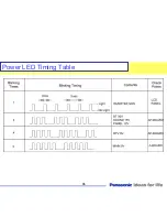
Page 35: ...35 Power LED Timing Table ...
Page 36: ...36 Power LED Timing Table ...
Page 39: ...39 Check Point A Board ...
Page 48: ...Purposely Left Blank Purposely left blank ...
Page 63: ...2008 LCD Television Models TC 37LZ85U TC32LX85 LCD Display Television Technical Guide 63 ...
Page 69: ...TC37LZ85 Signal Circuit Block Diagram TC37LZ85 Signal Circuit Block Diagram 69 ...
Page 71: ...TC32LX85 Signal Circuit Block Diagram TC32LX85 Signal Circuit Block Diagram 71 ...
Page 73: ...TC37LZ85 Audio Circuit Block Diagram TC37LZ85 Audio Circuit Block Diagram 73 ...
Page 75: ...TC32LX85 Audio Circuit Block Diagram TC32LX85 Audio Circuit Block Diagram 75 ...
Page 77: ...Power Supply Overview Power Supply Overview 77 ...
Page 78: ...TC TC 37LZ85 Power Supply Description 37LZ85 Power Supply Description 78 ...
Page 80: ...Self Self Check and Reset Function Check and Reset Function 80 ...
Page 81: ...SOS and Power LED Indication SOS and Power LED Indication 81 ...
Page 106: ...Internal Pattern Generator 1 Internal Pattern Generator 1 106 ...
Page 107: ...Internal Pattern Generator 2 Internal Pattern Generator 2 107 ...
Page 108: ...Internal Pattern Generator 3 Internal Pattern Generator 3 108 ...
Page 109: ...Copy data to SD card 1 Copy data to SD card 1 109 ...
Page 110: ...Copy data to SD card 2 Copy data to SD card 2 110 ...
Page 111: ...Copy data to SD card 3 Copy data to SD card 3 111 ...
Page 112: ...Copy data to SD card 4 Copy data to SD card 4 112 ...
Page 113: ...Copy data to SD card 5 Copy data to SD card 5 113 ...
Page 114: ...Copy data to SD card 6 Copy data to SD card 6 114 ...
Page 115: ...Copy Data from the SD Card to the TV 1 Copy Data from the SD Card to the TV 1 115 ...
Page 116: ...Copy Data from the SD Card to the TV 2 Copy Data from the SD Card to the TV 2 116 ...
Page 117: ...Copy Self Check Data to the SD Card 1 Copy Self Check Data to the SD Card 1 117 ...
Page 118: ...Copy Self Check Data to the SD Card 2 Copy Self Check Data to the SD Card 2 118 ...
Page 119: ...Copy Self Check Data to the SD Card 3 Copy Self Check Data to the SD Card 3 119 ...
Page 120: ...Local Maintenance 1 Local Maintenance 1 120 ...
Page 121: ...Local Maintenance 2 Local Maintenance 2 121 ...
Page 122: ...Local Maintenance 3 Local Maintenance 3 122 ...
Page 123: ...Local Maintenance 4 Local Maintenance 4 123 ...
Page 124: ...Local Maintenance 5 Local Maintenance 5 124 ...
Page 125: ...Local Maintenance 6 Local Maintenance 6 125 ...
Page 126: ...Local Maintenance 7 Local Maintenance 7 126 ...
Page 127: ...Local Maintenance 8 Local Maintenance 8 127 ...
Page 128: ...Picture Refresh Mode Picture Refresh Mode 128 ...