background image

© Panasonic Industrial Devices SUNX Co., Ltd. 2016

67

Chapter 5  Software Tool

CAUTION

Connections to this device via USB are assumed to include temporary connections for e.g., set-

tings and diagnoses. Constant connections via USB are not allowed.

<Reference>

The available functions vary depending on the version of 

SF-C21

 software and software tool 

Configurator SF-C

.”

For details, refer to “

2-4-1  Version-related Information

.”

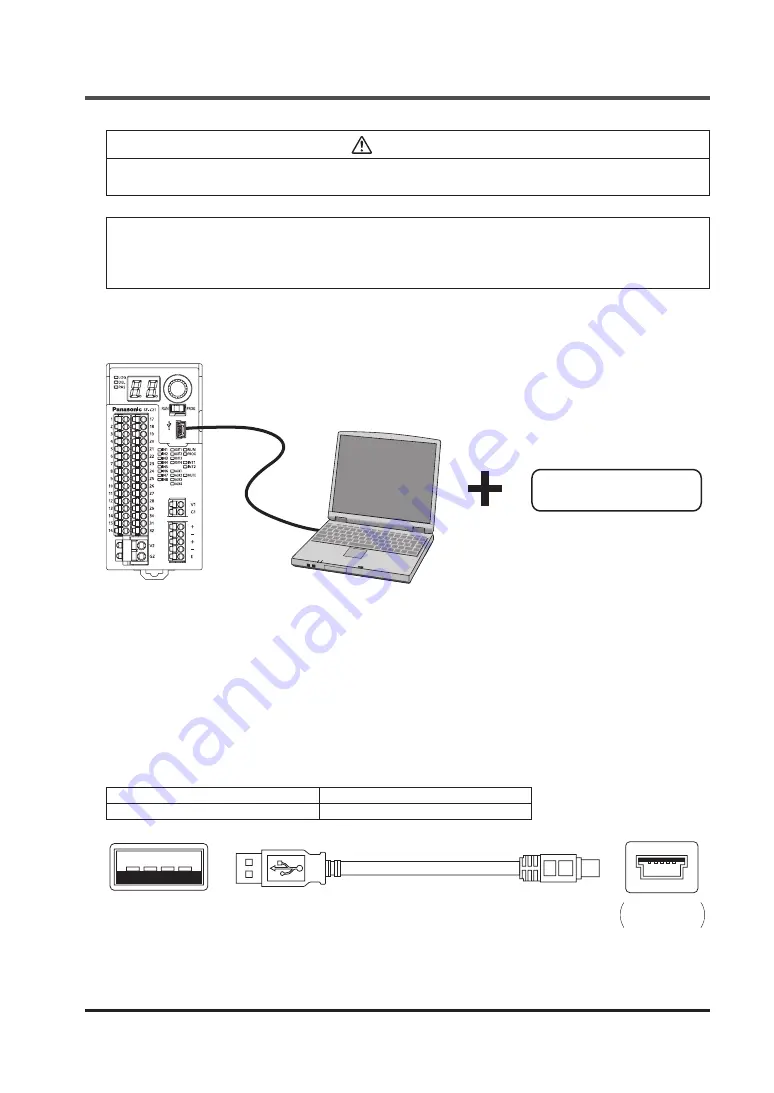
5-1  System Configuration

1. Software tools

3. PC

2. USB cable

1. Software tool “Configurator SF-C”

Exclusive for this device.

It is used for logic settings, diagnoses, and preparation of documents.

The software tool is downloadable at our website.

URL:  http://www3.panasonic.biz/ac/j/dl_center/software/index.jsp?c=search

In addition to “Narrow down by Part No. / Model No. format”, use “

SF-C21

” for searching.

2. USB cable

Use a USB cable available in the market.

Type of cable

Length

USB 2.0 cable (A: miniB)

3m or less

USB A type (male)‒  USB miniB type (5 pin, male)

(On the side of PC)

On the side 

of this device

Summary of Contents for SF-C21

Page 1: ...2016 1 panasonic net id pidsx global Safety Control Unit SF C21 Instruction Manual WUME SFC21 4 ...

Page 2: ... Panasonic Industrial Devices SUNX Co Ltd 2016 2 MEMO ...

Page 3: ...ance or disposal Please fully understand Safety Standards introduced in this instruction manual and properly handle the equipment with paying attention to the safety Notes 1 All the contents of this instruction manual are the copyright of the publishers and may not be reproduced even extracts in any form by any electronic or mechanical means including photocopying recording or information storage ...

Page 4: ...5 Installation Environment 19 2 6 Wiring 20 2 6 1 Power Supply Unit 20 2 6 2 I O Circuit Diagrams 21 2 6 3 Connecting to the Terminal Block 23 2 6 4 Connection of Safety Devices 24 Chapter 3 Functions 25 3 1 Safety Input 25 3 1 1 Contact Input Mismatch Allowable Time 25 3 2 Control Output 26 3 2 1 Response Time 26 3 3 Auxiliary Output 26 3 4 Interlock Reset 27 3 4 1 Overall Reset 27 3 4 2 Partial ...

Page 5: ...tem Specifications 68 5 2 1 Operating System 68 5 2 2 PC Specifications 68 5 3 Installation 68 5 4 Uninstallation 68 5 5 Connection of this Device and a PC 69 5 5 1 Connection to Monitor Mode 69 5 5 2 Connection to Transfer Mode 70 5 5 3 Setting to Monitor Mode after the End of Transfer 71 5 5 4 Disconnection of this Device from a PC 71 5 5 5 Initialization of this Device 71 5 6 Startup and End of...

Page 6: ...led Settings Muting 104 5 18 Logic Display Edit 105 5 19 Verify Files on the Device and PC 105 5 20 Configuration Check 106 5 21 Highlighting OFF 107 5 22 Device Information 107 5 22 1 General 107 5 22 1 1 Change Password 107 5 22 1 2 Initialize Settings 108 5 22 1 3 Initialize Password 108 5 22 2 Configuration Log 109 5 22 3 Error Log 109 5 23 Communication Settings 110 5 24 Monitor 111 5 25 Help...

Page 7: ...or industrial use only Use of this device under the following conditions or environments is not presupposed Please consult us if there is no other choice but to use this device in such an environment 1 Operating this device under conditions or environments not described in this manual 2 Using this device in the following fields nuclear power control railroad aircraft auto mo biles combustion facil...

Page 8: ...ur due to sudden changes in temperature 3 The ambient air contains corrosive or flammable gas 4 There is a high level of dust metallic dust or salt content 5 The device may be exposed to organic solvents such as benzene thinner or alcohol and or strong al kaline substances such as ammonia or caustic soda or any such substances exist in the ambient air 6 The device may be directly exposed to vibrat...

Page 9: ...1010 2 201 CAN CSA C22 2 No 61010 2 201 UL 1998 Regarding EU Machinery Directive a Notified Body TÜV SÜD has certified with the type exam ination certificate With regard to the standards in US Canada a NRTL TÜV SÜD has certified for CTÜVUS Mark Reference The conformity to JIS for this device has been evaluated by ourselves The CTÜVUS mark indicates that this device conforms to NRTL certification s...

Page 10: ...tactor Safety certified Logic selection Fixed 1 to 8 Customization 0 PC SF C21 1 Selecting preset logics and connecting various safety devices This device incorporates eight preset logics supporting basic applications and one customiz able logic that can be set freely 2 Easy setting of software tool and customizable logic Customizable logics can easily be set in PC by using a software tool 3 Acqui...

Page 11: ...aced 7 Fail safe function If a failure occur inside this device the self diagnosis function can detect the failure and turn OFF the output 8 Enhancement of failure diagnosis Failures including those of safety devices in connection is diagnosed by using test pulse monitoring of cross short fault In addition self diagnosis e g memory diagnosis and cir cuit diagnosis is performed 9 Installation accor...

Page 12: ...Indicator name Display Operation Logic selection indicator Orange LOG When logic is selected lights up in orange Other cases turn OFF Delay selection indicator Orange DEL When OFF delay is selected lights up in orange Other cases turn OFF Password selection indicator Orange PAS When password is selected lights up in orange Other cases turn OFF 7 segment indicator Red Selected logic OFF delay mode ...

Page 13: ...tput 19 IN6 Safety input 6 20 T6 Safety input 6 test output 21 IN7 Safety input 7 22 T7 Safety input 7 test output 23 IN8 Safety input 8 24 T8 Safety input 8 test output 25 MUTE2 Muting indicator output 1_2 26 NC Not connected 27 INT21 Reset input 2 test output 28 INT22 Reset input 2 29 OUT1 Control output 1 30 OUT2 31 OUT3 Control output 2 32 OUT4 Terminal block for in ternal power supply V1 24V ...

Page 14: ...SF C have been changed due to addition change of functions The added changed functions are supported by the versions shown in the table below Function Added changed Compatible version Remarks SF C21 software Configurator SF C Input filter Added Ver 2 00 and newer Ver 2 00 and newer Settings cannot be made unless the function is supported by both software ver sions Dedicated exit muting Added Seque...

Page 15: ...s device directly Doing so could cause malfunction or failure of this device Do not drop or apply strong impact on the case of this device which is made of resin Doing so could cause damage to it Fix this device with the DIN rail or screws securely Install this device on a flat surface Installing it on an uneven surface applies excessive force to internal parts resulting in a failure In case of di...

Page 16: ... 50mm or more 50mm or more 50mm or more Do not install the unit above devices which generate heat such as heaters transformers or large scale resistors In order to eliminate any effects from noise emission power wires and electromagnetic devices should be kept at 100mm or more away from the surfaces of the device When installing the unit behind the doors of the control board be especially careful ...

Page 17: ... Panasonic Industrial Devices SUNX Co Ltd 2016 17 Mounting To connect the software tool and cables keep a space of 170mm or more away from the instal lation surface of this device 170mm or more SF C21 ...

Page 18: ... the DIN rail stopper side of the unit with the DIN rail by pressing it in 1 2 3 Removing Step 1 Insert the flat head screwdriver into the groove in the DIN rail stopper Step 2 Draw out the DIN rail stopper Step 3 Push up the control unit toward the opposite side of the DIN rail stopper Step 4 Remove the control unit by pulling its lower side while maintaining it in the pushed up position step 3 1...

Page 19: ...ith a torque of 1 2N m or less M4 pan head screws length 12mm or more 37 M4 82 Mounting hole finished size Unit mm 2 5 5 Installation Environment For the installation environment refer to 8 1 Specifications Use the unit as per its specifications Installation place The unit is designed for use in a control panel Ambient temperature 10 to 55 C Ambient humidity 30 to 85 RH No dew condensation Polluti...

Page 20: ...low 1 Power supply unit authorized in the region where this device is to be used 2 Power supply unit SELV safety extra low voltage PELV protected extra low voltage conforming to EMC Directive and Low voltage Directive In case CE Marking conformity is required 3 Power supply unit conforming to the Low voltage Directive and with an output of 100VA or less 4 The frame ground F G terminal must be conn...

Page 21: ...xternal device monitor V1 1 INT11 INT12 INT21 INT22 Main circuit V2 AUX1 2 3 4 OUT1 3 OUT2 4 G2 T1 3 5 7 IN1 3 5 7 T2 4 6 8 IN2 4 6 8 Load 4 7kΩ KA Reset KB 4 7kΩ MUTE2 MUTE1 G1 KA KB 1 Wired when muting function and override function are used Reference KA KB External device Forced guided relay magnetic contactor monitored valve etc ...

Page 22: ...FF signal is not fed back this device judges either the output circuit or wiring as er ror and the control output maintains OFF status CAUTION Perform the wiring with paying attention to the input response time of the machine to be connect ed to this device since the OFF signal of this device might cause malfunction Timing chart ON ON ON ON OFF OFF OFF OFF Control output 1 OUT1 Control output 1 OU...

Page 23: ...n To remove the wire draw it out while pressing the release button For a solid wire or a twisted wire lead wire to be used refer to the table below Terminal block name Terminal block model No Ferrule terminal Solid wire twisted wire With an insu lation sleeve mm2 Without an insulation sleeve mm2 Terminal length mm Solid wire mm2 Twisted wire mm2 AWG Stripped wire length mm Terminal block for I O 1...

Page 24: ...ng test pulse excluding semiconductor output devices such as light curtain The functions input output auxiliary output and reset of this device are automatically set by selecting preset logic Customizable logic can be created by changing preset logic in part or in whole by using the software tool Arbitrary logics independent of preset logic can also be created as customizable logics Reference Logi...

Page 25: ...their own outputs 1NO 1NC contact input With diagnosis The input devices connected to this device are diagnosed to detect earth fault short fault to V or cross short fault 1NC contact input Without diagnosis Devices as shown below can be connected 2NC 1NO 1NC or 1NC contact output type switch PNP transistor output sensor or switch Major connectable devices Emergency stop switch Door switch includi...

Page 26: ...iary Output This device is equipped with four auxiliary outputs as non safety monitor outputs In the case of selecting preset logic the setting is as follows AUX1 Negative logic of OUT1 OUT2 AUX2 Negative logic of OUT3 OUT4 AUX3 Reset trigger output AUX4 Lockout output Each auxiliary output operation can be changed to the following output operation by using the software tool For details refer to C...

Page 27: ...le 3 4 1 Overall Reset Overall reset preset logic No 1 2 3 6 7 and 8 The outputs of two systems of this device are reset by one operation Manual reset Momentary type switch is connected to between INT11 and INT12 Resetting operation can be performed by switching the switch contact from Close to Open Auto reset INT21 INT22 is short circuited If between INT21 and INT22 is not short circuited when po...

Page 28: ...al reset Change to auto reset can be made using soft ware tool Manual reset Momentary type switch is connected to between INT11 and INT12 and be tween INT21 and INT22 Resetting operation can be performed by switching the switch contact from Close to Open Auto reset Short circuit is made between INT11 and INT12 and between INT21 and INT22 Partial reset manual start INT11 INT21 INT12 INT22 With exte...

Page 29: ...ut circuit error turns this device into lockout status In this case appears in 7 segment indicator red In this case release lockout by operating the switch again to switch Close to Open With external device monitor INT11 INT21 INT12 INT22 Without external device monitor INT11 INT21 INT12 INT22 Partial reset auto start Alternate type switch is connected to between INT11 and INT12 Switching from Ope...

Page 30: ... of ISO 13849 1 When test input is effective the control output is turned into OFF status This function is not incorporated into preset logic This function is used for setting with the soft ware tool Refer to 5 11 1 Types of Inputs The switch for 1NC contact or PNP semiconductor output normally set to ON is connected Contact Close or output ON Test input invalid Contact Open or output OFF Test inp...

Page 31: ...ting range Factory default Interface RS 485 Maximum transmission distance 100m Data length 8 bits Communication preference setting Either DIP switches take or software tool takes precedence DIP switches take precedence Parity bit presence With or without With Parity bit type Odd even Odd Stop bit 1 bit 2 bits 1 bit Communication address 1 to 247 1 Baud rate 9 600 bps 19 200 bps 38 400 bps 57 600 b...

Page 32: ...se shielded twisted pair cables The transmission line cables shielded cables should be connected in a crossover fashion and grounded at one end Classification Conductor Insulator Cable diameter mm Applicable cable example Size Resistance value At 20 C Material Thickness mm Shielded twisted pair 0 5 mm2 AWG 20 or more Up to 33 4 Ω km Polyethylene Up to 0 5 Approx 7 8 Hitachi Cable Ltd KPEV S0 5 mm2...

Page 33: ...g coil output status 0x02 Reading relay input status 0x03 Reading holding register 0x81 Error in reading coil output status 0x82 Error in reading relay input status 0x83 Error in reading holding register 3 8 4 Error Codes Configuration of communication data Office No Function code Error code CRC 16 Error code Error code Description 0x01 Function code error 0x02 Address error 0x03 Data quantity err...

Page 34: ... Input block 1 0x1000 IN3 4 Input block 2 0x1001 IN5 6 Input block 3 0x1002 IN7 8 Input block 4 0x1003 LOGIC1 Control block 1 0x1100 LOGIC2 Control block 2 0x1101 LOGIC3 Control block 3 0x1102 ER1 Lockout history Latest 0x1200 ER2 Lockout history 1 save ago 0x1201 ER3 Lockout history 2 saves ago 0x1202 ER4 Lockout history 3 saves ago 0x1203 ER5 Lockout history 4 saves ago 0x1204 LR1 Logic No histo...

Page 35: ...number L CRC 16 H Message error judgment data CRC 16 L Response during normal operation Data Description Office No SF C21 equipment address Function code 0x01 Number of bytes of communication data Number of bytes of communication data Data 1 to be read Data to be read Data n to be read CRC 16 H Message error judgment data CRC 16 L Response during abnormal operation Data Description Office No SF C2...

Page 36: ...umber L CRC 16 H Message error judgment data CRC 16 L Response during normal operation Data Description Office No SF C21 equipment address Function code 0x02 Number of bytes of communication data Number of bytes of communication data Data 1 to be read Data to be read Data n to be read CRC 16 H Message error judgment data CRC 16 L Response during abnormal operation Data Description Office No SF C21...

Page 37: ...judgment data CRC 16 L Response during normal operation Data Description Office No SF C21 equipment address Function code 0x03 Number of bytes of communication data Number of bytes of communication data Data 1 to be read H Data to be read Data 1 to be read L Data n to be read H Data n to be read L CRC 16 H Message error judgment data CRC 16 L Response during abnormal operation Data Description Off...

Page 38: ...assumed to include temporary connections for e g logic settings and diagnoses Constant connections via USB are not allowed When this device is connected to PC via a USB cable various information of this device can be transmitted and received by using the software tool Configurator SF C For details refer to Chapter 5 Software Tool ...

Page 39: ... IN2 2NC contact input IN5 IN6 2NC contact input IN3 IN4 2NC contact input IN7 IN8 2NC contact input Control output OUT1 2 Interlock Overall reset OFF delay 0 sec Note 1 OUT3 4 Interlock Overall reset OFF delay 0 sec Note 2 Auxiliary output AUX1 Negative logic of OUT 1 2 AUX3 Reset trigger AUX2 Negative logic of OUT 3 4 AUX4 Lockout Notes 1 Fixed at 0 sec 2 Time can be selected using this device F...

Page 40: ...X2 Negative logic of OUT 3 4 AUX4 Lockout Notes 1 Fixed at 0 sec 2 Time can be selected using this device For details refer to 3 11 OFF Delay Time Selection Function Timing chart When auto reset is set IN1 IN3 IN5 IN7 IN2 IN4 IN6 IN8 T1 T3 T5 T7 T2 T4 T6 T8 OUT1 2 OUT3 4 Closed Closed Closed Closed ON ON ON ON ON ON ON ON Open Open Open Open OFF OFF OFF OFF OFF OFF OFF OFF 100ms or less 100ms or l...

Page 41: ...Negative logic of OUT 3 4 AUX4 Lockout Notes 1 Fixed at 0 sec 2 Time can be selected using this device For details refer to 3 11 OFF Delay Time Selection Function Timing chart When auto reset is set IN1 IN3 IN5 IN7 IN2 IN4 IN6 IN8 T1 T3 T5 T7 T2 T4 T6 T8 OUT1 2 OUT3 4 Closed Closed ON ON ON ON ON ON ON ON ON ON Open Open OFF OFF OFF OFF OFF OFF OFF OFF OFF OFF MUTE OVERRIDE 100ms or less 100ms or ...

Page 42: ...egative logic of OUT 1 2 AUX3 Reset trigger AUX2 Negative logic of OUT 3 4 AUX4 Lockout Notes 1 Fixed at 0 sec 2 Time can be selected using this device For details refer to 3 11 OFF Delay Time Selection Function Timing chart Manual reset standard setting IN1 IN3 IN5 IN7 IN2 IN4 IN6 IN8 T1 T3 T5 T7 T2 T4 T6 T8 OUT1 2 OUT3 4 Closed Closed Closed Closed Closed Closed Closed Closed Closed Closed ON ON...

Page 43: ...egative logic of OUT 1 2 AUX3 Reset trigger AUX2 Negative logic of OUT 3 4 AUX4 Lockout Notes 1 Fixed at 0 sec 2 Time can be selected using this device For details refer to 3 11 OFF Delay Time Selection Function Timing chart Manual reset standard setting IN1 IN3 IN5 IN7 IN2 IN4 IN6 IN8 T1 T3 T5 T7 T2 T4 T6 T8 OUT1 2 OUT3 4 Closed Closed Closed Closed Closed Closed Closed Closed Closed Closed ON ON...

Page 44: ... Overall reset OFF delay 0 sec Note 2 Auxiliary output AUX1 Negative logic of OUT 1 2 AUX3 Reset trigger AUX2 Negative logic of OUT 3 4 AUX4 Lockout Notes 1 Fixed at 0 sec 2 Time can be selected using this device For details refer to 3 11 OFF Delay Time Selection Function Timing chart When auto reset is set Within 100ms Within 100ms Within 100ms Within 100ms Within 0 5 sec Within 0 5 sec 10ms or l...

Page 45: ... sec Note 2 Auxiliary output AUX1 Negative logic of OUT 1 2 AUX3 Reset trigger AUX2 Negative logic of OUT 3 4 AUX4 Lockout Notes 1 Fixed at 0 sec 2 Time can be selected using this device For details refer to 3 11 OFF Delay Time Selection Function Timing chart When auto reset is set IN1 IN3 IN5 IN7 IN2 IN4 IN6 IN8 T1 T3 T5 T7 T2 T4 T6 T8 OUT1 2 OUT3 4 Closed Closed Closed Closed Closed Closed Close...

Page 46: ... 4 Interlock Overall reset OFF delay 0 sec Note 2 Auxiliary output AUX1 Negative logic of OUT 1 2 AUX3 Reset trigger AUX2 Negative logic of OUT 3 4 AUX4 Lockout Notes 1 Fixed at 0 sec 2 Time can be selected using this device For details refer to 3 11 OFF Delay Time Selection Function Timing chart When auto reset is set IN1 IN3 IN5 IN7 IN2 IN4 IN6 IN8 T1 T3 T5 T7 T2 T4 T6 T8 OUT1 2 OUT3 4 Closed Cl...

Page 47: ...1 OFF Delay Time Selection Function The OFF delay times that this device can set are as follows No OFF delay time Stop category 0 0 sec 0 1 0 1 sec 1 2 0 5 sec 3 1 sec 4 2 sec 5 5 sec 6 10 sec 7 15 sec 8 30 sec 9 60 sec Note Only OUT3 4 can be set with this device ...

Page 48: ...d to 60 sec in units of 0 01 sec 1 sec Input filter time ON OFF 0 to 1 sec in units of 0 01 sec 0 sec OFF ON ON delay time 0 to 5 940 sec in units of 0 1 sec 0 sec OFF delay time 0 to 60 sec in units of 0 1 sec 0 sec Allowable time difference in muting input Parallel muting 1 to 10 sec in units of 1 sec 3 sec Sequential muting 0 unlimited to 288 000 sec in units of 1 sec 288 000 sec Muting duratio...

Page 49: ...ed and started manually The logics of this device are stopped according to the procedure below Step 1 Switch the mode selector switch to the PROG side Step 2 Press the rotary switch The logics of this device are started according to the procedure below Step 1 Switch the mode selector switch to the RUN side Step 2 Press the rotary switch ...

Page 50: ... Logic 0 Customizable logic 1 Overall stop control 2 Parallel muting control 3 Sequential muting control 4 Partial stop control 1 5 Partial stop control 2 6 Two hand control 7 OR control 8 Operation mode selection control OFF delay times and stop categories corresponding to Nos are shown in the table below No OFF delay time Stop category 0 0 sec 0 1 0 1 sec 1 2 0 5 sec 3 1 sec 4 2 sec 5 5 sec 6 10...

Page 51: ... the indicators one by one After the end of initial diagnosis the operation indicator green lights up If a terminal block is connected only to the power supply auxiliary output indicator 1 2 4 or ange and interlock indicator 1 2 yellow light up The other indicators turn OFF Pressing the rotary switch displays factory setting in the 7 segment indicator red turning ON the logic selection indicator o...

Page 52: ...ss the rotary switch The logic No currently set is displayed in the 7 segment indicator red Logic selection indicator orange lights up Overall stop control is set at factory 3 Rotate the rotary switch The currently set No for OFF delay time is displayed in the 7 segment indi cator red Delay selection indicator orange lights up 0 sec is set at factory Rotating the rotary switch returns to No 1 4 Lo...

Page 53: ...ation The power saving function of this device turns OFF the 7 segment indicator red 3 sec after power ON the end of initial diagnosis or final operation 2 Occurrence of abnormality Example internal failure two inputs short circuit ed etc If an error occurs an error code is displayed in the 7 segment indicator red and dots blink Either one of error codes to and is displayed in the 7 segment indica...

Page 54: ...ow in the figure below PROG mode Indicator ON confirmation Password entry Select set mode Select operation setting Set logic Set OFF delay time Set password Confirm Password Return to Set password Write confirm password Return to Select operation setting Return to Select operation setting Confirm operation setting Return to Select operation setting Write confirm operation setting End of setting YE...

Page 55: ...turns OFF the 7 segment indicator red 3 sec after power ON the end of initial diagnosis or final operation 2 Switch the mode selector switch to the PROG side This device transitions to PROG mode The operator indicator green turns OFF The setting indicator orange blinks 3 This device automatically transitions to Indicator ON confirmation Individual segments of the 7 segment indicator red light up o...

Page 56: ... select a number by rotating the rotary switch 9 Select password 2 from to Determine the password 2 by pressing the rotary switch When password 1 and password 2 are correct proceed to Step 11 When password 1 or 2 is incorrect proceed to Step 10 10 is displayed in the 7 segment indicator red Pressing the rotary switch returns to Step 5 Enter the password again 11 Transition to Select setting mode P...

Page 57: ... switch proceeds to Step 21 14 The currently set No for OFF delay time is displayed in the 7 segment indi cator red Delay selection indicator orange blinks 0 sec is set at factory Rotating the rotary switch returns to Step 13 Pressing the rotary switch proceeds to Step 18 Holding down the rotary switch proceeds to Step 21 15 Transition to Set logic The logic No currently set is displayed in the 7 ...

Page 58: ...rns to Step 21 18 Transition to Set OFF delay time The current No for OFF delay time is displayed in the 7 segment indicator red and blinks 19 Rotate the rotary switch to select OFF delay time from to 20 As an example is selected Press the rotary switch for the determination and return to Step 14 Holding down the rotary switch determines the selection and then returns to Step 21 21 Transition to C...

Page 59: ...he rotary switch changes the display to that shown in the il lustration at left In the 7 segment indicator red indicating OK is displayed The logic selection indicator orange and delay selection indicator orange blink Transition to Write confirm operation setting The logic and OFF delay time set in this device have been changed Releasing the hand from the rotary switch proceeds to the next step 25...

Page 60: ...F Delay Time Step Status of indicators and switches Description 28 Switch the mode selector switch to the RUN side The operation indicator green blinks Press the rotary switch 29 The operation indicator green status changes to lighting up This device transitions to RUN status ...

Page 61: ...tor ON confirmation Password entry Select set mode Select operation setting Set logic Set OFF delay time Set password Confirm password Return to Set password Write confirm password Return to Select operation setting Return to Select operation setting Confirm Set operation setting Return to Select operation setting Write confirm operation setting End of setting YES YES NO NO NO NO YES YES ...

Page 62: ...ator red 3 sec after power ON the end of initial diagnosis or final operation 2 Switch the mode selector switch to the PROG side This device transitions to PROG mode The operation indicator green turns OFF The setting indicator orange blinks 3 This device automatically transitions to Indicator ON confirmation Individual segments of the 7 segment indicator red light up one by one Check for an error...

Page 63: ...word 2 Similarly select a number by rotating the rotary switch 9 Select password 2 from to Determine password 2 by pressing the rotary switch When password 1 and password 2 are correct proceed to Step 11 When password 1 or 2 is incorrect proceed to Step 10 10 is displayed in the 7 segment indicator red Pressing the rotary switch returns to Step 5 Enter the password again 11 Transition to Select se...

Page 64: ...ayed in the the 7 segment indicator red 14 Set password 1 Select a number by rotating the rotary switch Select password 1 from to As an example select for password 1 and then determine it by press ing the rotary switch 15 Password 2 is displayed in the the 7 segment indicator red Set password 2 Similarly select a number by rotating the rotary switch 16 Select password 2 from to As an example selec...

Page 65: ...1 and 2 again 20 Holding down the rotary switch changes the display to that shown in the il lustration at left In the 7 segment indicator red indicating OK is displayed Password selection indicator orange blinks Transition to Write confirm password The passwords of this device have been changed Releasing the hand from the rotary switch proceeds to the next step 21 After the end of write operation ...

Page 66: ...indicators and switches Description 23 Transition to Quit setting mode 24 Switch the mode selector switch to the RUN side The operation indicator green blinks Press the rotary switch 25 The operation indicator green status changes to lighting up This device transitions to RUN status ...

Page 67: ...lated Information 5 1 System Configuration 1 Software tools 3 PC 2 USB cable 1 Software tool Configurator SF C Exclusive for this device It is used for logic settings diagnoses and preparation of documents The software tool is downloadable at our website URL http www3 panasonic biz ac j dl_center software index jsp c search In addition to Narrow down by Part No Model No format use SF C21 for searc...

Page 68: ... port 5 3 Installation Double click downloaded ConfiguratorSF C_v Install the program according to the instruction of the installation program This installation program requires two installations installation of software tool and installation of USB driver for this device If a warning message for Windows e g User account control or Publisher of the driver soft ware cannot be verified may be displa...

Page 69: ...e rotary switch If the connection is made for the first time press the rotary switch after the completion of USB driver installation 3 The device enters Monitor mode The operation indicator green lights up In Monitor mode the software tool is used to read data from and monitor this device Monitor mode prevents writing data into this device When writing data into this device refer to Procedure 5 5 ...

Page 70: ... indicator orange blinks 2 This device automatically transitions to Indicator ON confirmation Individual segments of the 7 segment indicator red light up one by one Check for an error code displayed in the 7 segment indicator red Press the rotary switch 3 The device enters Transfer mode Transfer mode disables setting operation on the side of this device The software tool is used for example to tra...

Page 71: ...ce Monitor mode prevents writing data into this device When writing data into this device again refer to Procedure 5 5 2 Connection to Transfer Mode 5 5 4 Disconnection of this Device from a PC When the USB cable is unplugged from this device it can be disconnected from the PC The USB cable can be unplugged except when logic is being transferred by the software tool When the mode selector switch i...

Page 72: ...re below Step 1 Click the Start button in Windows Step 2 From All Programs go to Panasonic ID SUNX Safety and Configurator SF C in or der and then select Configurator SF C Step 3 Starting up the software tool Configurator SF C displays the main menu and selec tion menu From the selection menu select one of the following four operations Create a new file Open sample logic Open a recent file Upload ...

Page 73: ... sample logic displays the Open sample logic screen Eight preset logics provided to this device can be used as sample logics Select one from preset logics No 1 to No 8 Sample logics are revised to create logics To Open files saved Pressing Open a recent file displays the Open file screen Select a file to be opened To obtain a logic from this device in con nection Pressing Upload logic from device ...

Page 74: ...td 2016 74 Startup and End of Software Tool 5 6 2 End of Software Tool To exit the software tool follow one of the methods below Method 1 From the menu bar select File F and then Exit X Method 2 Click at the upper right corner of the screen ...

Page 75: ...e 5 7 New Save Print of a File 5 7 1 Create New File New files are created by using one of the following methods Method 1 When the software tool starts up select Create a new file Method 2 From the menu bar select File F and then New N Method 3 Click New icon on the toolbar ...

Page 76: ... Panasonic Industrial Devices SUNX Co Ltd 2016 76 New Save Print of a File When a new file is created according to one of the methods the main screen is made clear ...

Page 77: ...pen Sample Logic Open sample logic is performed according to one of the following methods Method 1 When the software tool starts up select Open sample logic Method 2 From the menu bar select File F and then Open sample logic L Method 3 Click the Open sample logic icon on the tool bar ...

Page 78: ...c Industrial Devices SUNX Co Ltd 2016 78 New Save Print of a File When Open sample logic is displayed select a logic with the Previous and Next button and then press OK The logic is displayed in the main screen ...

Page 79: ...t of a File 5 7 3 Open a Recent File Existing files are opened by using one of the following methods Method 1 When the software tool starts up select Open a recent file Method 2 From the menu bar select File F and then Open O Method 3 Click Open icon on the toolbar ...

Page 80: ...Panasonic Industrial Devices SUNX Co Ltd 2016 80 New Save Print of a File When the file selection diagram is displayed select a file and click Open O Opening the file displays a logic in the main screen ...

Page 81: ... one of the following methods is performed Connect this device with a PC according to procedure 5 5 1 Connection to Monitor Mode Method 1 When the software tool starts up select Upload logic from device Method 2 From the menu bar select Device D and then Upload logic from device U Method 3 Click the Upload logic from device icon on the toolbar ...

Page 82: ... in the PC as a file The file format of the files to be created is specified to be file name sfc Select Save to save a file to the same file and select Save as to save under a new file name Save Files are saved by one of the following methods Method 1 From the menu bar select File F and then Save S Method 2 Click the Save icon on the toolbar ...

Page 83: ...nt of a File Save as Files are saved under new file names by one of the following methods Method 1 From the menu bar select File F and then Save as A Method 2 Click the Save as icon on the toolbar Specify a place to save the file and the file name and click Save S ...

Page 84: ...ion to Transfer Mode Step 1 Method 1 From the menu bar select Device D and then Download logic to device D Method 2 Click the Download logic to device icon on the toolbar Step 2 Diagnosing logic Diagnose the logic created This shows a display without error Click OK and proceed to the next step This shows a display with some error in the logic created Click OK to return to the main screen and then ...

Page 85: ...ck OK Logic is being transferred While being transferred do not remove the USB cable or do not turn OFF the power supply The file has been downloaded Click OK According to the procedures 5 5 3 Setting to Monitor Mode after the End of Transfer and 5 5 4 Disconnection of this Device from a PC return this device to the monitor mode and remove the USB cable ...

Page 86: ...y one of the following methods Method 1 From the menu bar select File F and then Print P Method 2 Click the Print icon on the toolbar When the print dialog is displayed select a printer and perform printing Preview is displayed on the backside of the dialog box The contents can be confirmed before printing ...

Page 87: ...ontrol block 2 Control block 3 Connection tab 2 Connection tab 3 Connection tab 4 Connection tab 5 Input block 2 Input block 3 Input block 4 Toolbar Mode switching block Interlock block Auxiliary output block Logic edit block Menu bar All the operations and functions of the software tool are prepared in a menu format according to various applica tions Toolbar Frequently used functions are displaye...

Page 88: ... muting control or sequential muting con trol activates detailed settings allowing required detailed items to be set in muting Control block 2 3 Required logic is selected from AND OR and no logic Interlock block Overall reset partial reset manual start and partial reset auto start are carried out Auxiliary output block Settings of auxiliary output can be changed The results of the monitoring of i...

Page 89: ...tial muting Two hand control and Input select editing an applicable logic by opening it is easier than by creating a new logic Open a recent file and edit it When a logic has already been created open a recent file and edit it according to 5 7 3 Open a Recent File Obtain a logic from this device and edit it According to 5 7 4 Upload Logic from this Device obtain the logic which is being used in th...

Page 90: ... 10 1 Create a Logic As an example sample logic No 1 is created from the new screen 5 10 1 1 Set Input Lock Click input block 1 and open Input select Click 2NC at the upper left portion Selected 2NC is set in input block 1 Similarly set input blocks 2 3 and 4 Set all input blocks to 2NC ...

Page 91: ...reate a Logic 5 10 1 2 Set Control Block 1 Click control block 1 and open Select control Click AND at the upper left portion Selected AND is set in control block 1 5 10 1 3 Create a Circuit Click A of connection tab 1 to connect it to A of input block 1 ...

Page 92: ...b 1 to connect it to B of input block 2 Click C to connect it to C of input block 3 Click D to connect it to D of input block 4 Click E of connection tab 4 to connect it to E of connection tab 1 Click E of connection tab 5 to connect it to E of connection tab 1 Sample logic No 1 is created completely ...

Page 93: ...it to C of input block 3 Click D to connect it to D of input block 4 Click A of connection tab 2 to connect it to A of input block 1 Click B to connect it to B of input block 2 Click F of connection tab 4 to connect it to F of connection tab 2 Click E of connection tab 5 to connect it to E of connection tab 1 The following logic is created Output block 1 outputs the AND of input blocks 1 and 2 Out...

Page 94: ...ND Selected AND is set in control block 3 Click the following portions to perform wiring Click E of connection tab 3 to connect it to E of connection tab 1 Click F to con nect it to F of connection tab 2 Click G of connection tab 4 to connect it to G of connection tab 3 Click E of connection tab 5 to connect it to E of connection tab 1 The following logic is created Output block 1 outputs the AND ...

Page 95: ...n control block 1 This connects two mute sensors dif each of which has NO and NC contacts or output PNP semiconductor output When Sequential muting is set in control block 1 both Muting input equ and Muting input dif cannot be used at a time Override Used as the input of override switch when it is selected as Parallel muting or Sequential mut ing in control block 1 Connects a momentary type switch...

Page 96: ...this device is specified to be category 2 or less No logic If the number of safety devices in connection is less than 4 they are used for unused input block If a safety device is connected the operation is not reflected Reference For the connectable input blocks and combinations of them with control blocks refer to 5 20 Configuration Check 5 11 2 Setting of Contact Input Mismatch Allowable Time Se...

Page 97: ...ilter time for ON to OFF and OFF to ON is set for the prevention of erratic operations caused by input chattering and noise Settable range Initial setting Input filter time ON OFF 0 to 1 sec in units of 0 01 sec 0 sec OFF ON CAUTION If the input filter time ON OFF is set the OFF response time for control output becomes 10ms input filter time ON OFF or less ...

Page 98: ...ed muting input block the IN with the smaller number is set as muting input A and the IN with the larger number is set as muting input B If input block 3 is set and connected as a muting input IN5 becomes muting input A and IN6 be comes muting input B Sequential muting Used when Sequential muting is performed In the two connected muting input blocks INs are set as muting input A muting input B mut...

Page 99: ...onnected to control blocks and one of them is specified to be key se lector If input block 2 and input block 4 are set as inputs to be selected and input block 3 is set and connected to the key selector input input block 2 is selected when IN5 is OFF and IN6 is ON and input block 4 is selected when IN5 is ON and IN6 is OFF Reference For the connectable input blocks and combinations of them with co...

Page 100: ...et by one operation Manual reset Momentary type switch is connected to between INT11 and INT12 Switching the switch contact from Closed to Open performs reset operation Auto reset Short circuit is generated between INT21 and INT22 If INT21 INT22 is not short circuited when power is turned ON manual reset is automatically selected Partial reset Each of the outputs of two systems of this device is r...

Page 101: ...ive logic of OUT3 OUT4 AUX3 Reset trigger output AUX4 Lockout output MUTE Muting indicator output fixed The following operations can be set in auxiliary out puts Positive logic output or negative logic output of OUT1 OUT2 Positive logic output or negative logic output of OUT3 OUT4 Output A B C D of diagnosis results of input block 1 2 3 4 Output E F G of diagnosis results of internal logical circu...

Page 102: ...exists the message at right is dis played Pressing OK returns to edit mode in the main screen highlighting the control block and connection tab in red frames If no error exists the message at right is dis played Pressing OK transitions to simulation mode in the main screen Transition to simulation mode has been per formed As an example sample logic No 1 is used In the case of overall reset click t...

Page 103: ...1 of input block 1 It turns light color This indicates that the contact is closed In all input blocks click In OUT1 to OUT4 turns light color This indicates that the output is in ON status Click Edit mode of the mode switching block to terminate simulation mode Transition to edit mode ...

Page 104: ...or Sequential muting in control block 1 Clicking Details opens Detailed settings Allowable time difference in muting input Dura tion Exit only muting time Note and Input pri ority for muting and Duration for override are set Setting range Initial setting Allowable time difference in muting input Parallel muting 1 to 10 sec in units of 1 sec 3 sec Sequential muting 0 Unlimited to 288 000 sec in uni...

Page 105: ...ock opens Logic display edit screen The customizable logic No displayed on the 7 segment display of the device can be set 5 19 Verify Files on the Device and PC Logic created in the main screen is compared with the customizable logic of this device If a difference exists the target input block control block and connection tab are highlighted in white frames ...

Page 106: ... 1NO 1NC PNP 2 equ Note 1 Note 1 PNP 2 dif Note 1 Note 1 Muting input equ Note 2 Note 3 Muting input dif Note 2 Note 3 Override Key selector PNP 1 1NC Test No logic Notes 1 For either PNP 2 equ or PNP 2 dif only one connection is allowed 2 For either Muting input equ or Muting input dif only one connection is allowed 3 For either Muting input equ or Muting input dif two connections are allowed Com...

Page 107: ...performed From the menu bar select Device D and then Device information I 5 22 1 General Clicking General tab displays device name device Ver serial No and current logic No Password change and initialization of set tings can be performed 5 22 1 1 Change Password Clicking Change password displays Change password After the password is entered clicking OK changes the password to new one If the passwo...

Page 108: ... device in Write mode according to 5 5 1 Connection to Monitor Mode or 5 5 2 Connection to Transfer Mode Step 2 From the menu bar select Device D and then Device information I to open De vice information Step 3 Click the General tab Initialize Settings Step 4 When Confirm password opens enter the password Step 5 Clicking OK performs initialization 5 22 1 3 Initialize Password Clicking Initialize p...

Page 109: ... log confirms logics transferred Five pieces information including the latest one can be confirmed Clicking the bar of a log to be confirmed opens a different screen allowing you to confirm the logic 5 22 3 Error Log Clicking Error log confirms logs of errors that occurred in the past The past 5 logs can be confirmed ...

Page 110: ...Communication Settings The communication settings of this device are made From the menu bar select Device D and then Communica tion settings C Baud rate parity bit stop bit and addresses can be set For details on communication settings refer to 3 8 MODBUS Communication Non safety ...

Page 111: ...24 Monitor The current status of this device can be monitored The monitoring operation is performed by one of the following methods Method 1 From the menu bar select File F and then Monitor M Method 2 Click the Monitor icon on the toolbar The monitor screen opens ...

Page 112: ...uage L Select a language in which the software tool is displayed If the language is changed the software must be restarted The logic which is being used for operation and has not yet been saved should be saved according to the dialog 5 25 2 Manual From the menu bar select Help H and then select User Manual M The manual written in the language currently selected is displayed 5 25 3 Version Informat...

Page 113: ... dirt or foreign matter deposited on them The corresponding connectors have been connected securely The unit is securely installed to the DIN rail or securely mounted by means of machine screws 6 2 Periodic Inspection Every Six Months WARNING Be sure to inspect the following items every six months and confirm that there is no error Operating this device without inspection or in an error condition ...

Page 114: ...as described below 1 When changes are made to the settings of the device 2 When any parts of this device are replaced 3 When some abnormality is felt during operation 4 When the device installation place or environment is changed 5 When the wiring method or wiring layout is changed 6 When a component or components of a FSD Final Switching Device to which the con trol output is connected are replac...

Page 115: ...F the blinking input block once and turn it ON within the input mismatch allowable time Wiring connecting safety contact or safety sensor is discon nected while safety input is ON One of duplex inputs is turned OFF Recheck the wiring of the safety inputs turn OFF the blinking input block and then turn it ON Interlock indicator yellow 1 2 lights up Cause Remedy Reset is not released Reset input ter...

Page 116: ...afety sensors in connection and replace them if necessary Control output circuit error When control output 1 2 is ON it is short circuited with 0 V or V Correctly wire control output 1 2 Refer to 2 6 Wiring When control output 1 2 is OFF it short circuits with V Control output terminals short cir cuit with each other or with other input output lines Excessive current flows in control output 1 2 Cu...

Page 117: ... voltage Same as voltage of the power supply for external Residual voltage 2 5V or less Leakage current 100μA or less Including power supply OFF condition Output mode Factory defaults AUX1 Negative logic of OUT1 OUT2 ON when OUT1 OUT2 is OFF AUX2 Negative logic of OUT3 OUT4 ON when OUT3 OUT4 is OFF AUX3 Reset trigger output ON under reset release wait condition AUX4 Lockout output OFF when lockout...

Page 118: ...t Between all supply terminals connected together and enclosure all out puts connected together all input connected together all outputs con nected together USB port All outputs connected together RS 485 port Insulation resistance 20MΩ or more with 500V DC mega All inputs connected together USB port all inputs connected together RS 485 port USB port RS 485 port Between all supply terminals connect...

Page 119: ... each other or with other I O Overcurrent flows in control output Internal circuit failure Applicable standards Safety IEC 61508 1 to 7 EN 61508 1 to 7 SIL3 ISO 13849 1 Up to category 4 PLe IEC 61131 2 IEC 61010 2 201 IEC 62061 SILCL3 UL 61010 1 UL 61010 2 201 UL 1998 EMC IEC 61000 6 2 IEC 61326 3 1 EN 55011 Related standards IEC 60947 1 IEC 60947 5 1 IEC 60947 5 2 IEC 60947 5 5 IEC 60947 5 8 IEC ...

Page 120: ... Panasonic Industrial Devices SUNX Co Ltd 2016 120 Specifications Dimensions 8 2 Dimensions Unit mm 37 45 5 85 4 7 82 30 4 6 90 27 5 19 25 Suitable for 35mm width DIN rail 2 ø4 4 ...

Page 121: ...rgy generated by surrounding electronic devices IEC 61508 1 to 7 JIS C 0508 1 to 7 The standards that pertain to general functional safety for electrical electronic and programmable electronic devices These standards are provided intended to serve as basic and me chanical safety standards that are applicable for various types of industries Functional safety is defined as the totally safe part that...

Page 122: ...mbH Panasonic Testing Center EU Representative s Address Winsbergring 15 22525 Hamburg Germany Product Safety Control Unit Model Name SF C21 Trade Name Panasonic Application of Council Directive 2006 42 EC Machinery Directive 2004 108 EC EMC Directive Valid until April 19 2016 2014 30 EU EMC Directive Valid from April 20 2016 2011 65 EU RoHS Directive Harmonized standards EN ISO 13849 1 2008 EN 62...

Page 123: ... Panasonic Industrial Devices SUNX Co Ltd 2016 123 Revision History First edition October 31 2014 Second edition December 25 2014 Third edition April 10 2015 Fourth edition January 15 2016 ...

Page 124: ... Panasonic Industrial Devices SUNX Co Ltd 2016 124 MEMO ...

Page 125: ...OR ANY INDIRECT INCIDENTAL SPECIAL OR CONSE QUENTIAL DAMAGES OF ANY KIND GENERAL TERMS AND CONDITIONS 4 OR ANY DAMAGES RESULT ING FROM LOSS OF USE BUSINESS INTERRUPTION LOSS OF INFORMATION LOSS OR INACCURACY OF DATA LOSS OF PROFITS LOSS OF SAVINGS THE COST OF PROCUREMENT OF SUBSTITUTED GOODS SERVICES OR TECHNOLOGIES OR FOR ANY MATTER ARISING OUT OF OR IN CONNECTION WITH THE USE OR INABILITY TO USE...

Page 126: ...Kasugai shi Aichi 486 0901 Japan Telephone 81 568 33 7861 Facsimile 81 568 33 8591 panasonic net id pidsx global For sales network please visit our website Panasonic Industrial Devices SUNX Co Ltd 2016 January 2016 PRINTED IN JAPAN WUME SFC21 4 Please contact ...

Reviews: