

INSTRUCTION MANUAL
Communication Unit for DeviceNet
SC-GU3-02
CMJE-SCGU302 No.0065-60V
For details of the communication commands etc. of the communication unit for
DeviceNet
SC-GU3-02
, refer to “
Product Specification
” or “
Communication
Command Specification
.”
1
CE MARKED PRODUCT
●
The models listed under “
8
SPECIFICATIONS
” come with CE Marking.
As for all other models, please contact our office.
2
OUTLINE
●
Communication unit
SC-GU3-02
can output the output signal (in case of 2-out-
put type, only the output 1) of a sensor amplifier (NPN output type) that is con
-
nectable to cascading connector unit
SC-71
(optional), as the communication
data of
DeviceNet
.
●
SC-GU3-02
enables to connect max. 16 units of sensor amplifier (
FX-300
se-
ries or
LS-400
series, etc.). In case of
FX-500
series or
LS-500
series, max.
12 units of sensor amplifier can be connected.
● This product can output all the output signals of the connected sensor amplifi
-
ers to PLC (Programmable Logic Controller) etc. in one time.
●
By using end unit
SC-GU3-EU
, settings and control of the connected optically com-
municationable sensor amplifier (
FX-500
series or
LS-500
series) can be done.
Sensor amplifier (Optional)
End unit
SC-GU3-EU
(Optional)
End plate
MS-DIN-E
(Optional)
Cascading connector unit
SC-71
(Optional)
End plate
MS-DIN-E
(Optional)
Communication unit for DeviceNet
SC-GU3-02
3
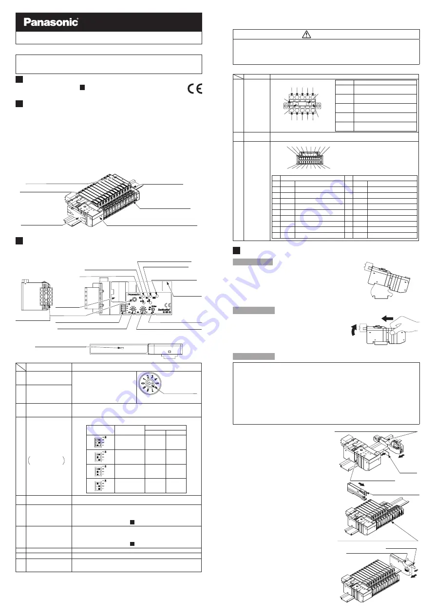
FUNCTIONAL DESCRIPTION
●
Communication unit for DeviceNet SC-GU3-02
8. Power indicator (Green)
9. ERR. indicator (Red)
10. Memory function
indicator (Yellow)
4. Operation mode setting switch
12. wire-saving
connector
11. Connector
for DeviceNet
15. parallel
output
connector
(with cover)
5. Setting extension key
1. Address setting switch (Tens digit)
2. Address setting switch (One digit)
3. Baud rate setting switch
6. MS indicator (Green/Red)
7. NS indicator (Green/Red)
●
End unit SC-GU3-EU
8. Power indicator (Green)
Designation
Function
1
Address setting switch
(Tens digit) (Note 3)
(Factory setting is 0)
To set address of DeviceNet.
Setting is possible in the range of 0
to 63 (64 or more: Error)
Setting direction of
switch
(Present setting is 0)
As for number displays on switches,
refer to each switch.
2
Address setting switch
(One digit) (Note 3)
(Factory setting is 1)
3
Baud rate setting switch
(Note 3)
(Factory setting is 500kbps)
To set baud rate of DeviceNet(bps) from 125K, 250K or 500K
4
Operation mode setting
switch (with cover)
Factory setting is
simple mode
Data amount of I/O message can be changed by this setting.
DIP switch
Operation mode
Occupied memory
IN
OUT
Standard mode
3 byte
0 byte
Simple mode
10 byte
10 byte
Full mode
10 byte
44 byte
Minimum mode
2 byte
0 byte
5
Setting extension key
(Note 3)
Used for memory function (Note 1), teaching and light intensity adjustment
(Note 2). Also, used for canceling communication error.
6
MS indicator (Green/Red)
Displays whether this product is operating properly or not
• Green LED lights up: Normal operation condition
• Lights off: Power OFF
For the detail of the error, refer to “
7
ERROR INDICATOR
”.
7
NS indicator (Green/Red)
Displays whether this product is communicating properly with DeviceNet or not
• Green LED lights up: Normal operation condition
• Lights off: Power OFF
For the detail of the error, refer to “
7
ERROR INDICATOR
”.
8
Power indicator (Green)
Lights up when power is ON.
9
ERR. indicator (Red)
Blinks when an optical communication error occurs.
10
Memory function
indicator (Yellow)
Lights up when using memory function.
Blinks when connecting a sensor amplifier whose set contents are different
from the ones that are storing in this product.
Notes: 1) in case using the memory function,
SC-GU3-EU
is required. Refer to “
Communication Command
Specification
” for detail of memory function.
2) For the teaching and memory function, refer to “
Communication Command Specification
”.
3) For changing the setting, use a flat-head screwdriver etc.
Thank you very much for purchasing Panasonic products. Read this Instruction
Manual carefully and thoroughly for the correct and optimum use of this product.
Kindly keep this manual in a convenient place for quick reference.
WARNING
●
Never use this product in a device for personnel protection.
●
In case of using devices for personnel protection, use products which meet
laws and standards, such as OSHA, ANSI or IEC etc., for personnel protec
-
tion applicable in each region or country.
Designation
Function
11
Connector for
DeviceNet
Terminal No.
Description
1
V- connecting terminal
(2 systems for cascade wiring)
2
CAN-L connecting terminal
(2 systems for cascade wiring)
3
Drain connecting terminal
(2 systems for cascade wiring)
4
CAN-H
connecting terminal
(2 systems for cascade wiring)
5
V+ connecting terminal
(2 systems for cascade wiring)
12
Wire-saving
connector
Connecting Wire-saving connector
SC-71
(optional) connected sensor amplifier.
13
Parallel
output
connector
(with cover)
Description
Description
1
Signal 0
Output info for 1ch amplifier
11 Signal 10
Output info for 11ch amplifier
2
Signal 1
Output info for 2ch amplifier
12 Signal 11
Output info for 12ch amplifier
3
Signal 2
Output info for 3ch amplifier
13 Signal 12
Output info for 13ch amplifier
4
Signal 3
Output info for 4ch amplifier
14 Signal 13
Output info for 14ch amplifier
5
Signal 4
Output info for 5ch amplifier
15 Signal 14
Output info for 15ch amplifier
6
Signal 5
Output info for 6ch amplifier
16 Signal 15
Output info for 16ch amplifier
7
Signal 6
Output info for 7ch amplifier
17
Open
Not used
8
Signal 7
Output info for 8ch amplifier
18
Open
Not used
9
Signal 8
Output info for 9ch amplifier
19
V+
V+
10 Signal 9
Output info for 10ch amplifier
20
V+
V+
4
MOUNTING AND CONNECTION
How to mount
1.
Fit the rear part of the mounting sec-
tion of the unit on a DIN rail.
2.
Press down the rear part of the mount
-
ing section of the unit on the DIN rail
and fit the front part of the mounting
section to the DIN rail.
How to remove
1.
Push the unit forward.
2.
Lift up the front part of the unit to re
-
move it.
Note: Take care that if the front part is lifted without push-
ing the unit forward, the hook on the rear portion of
the mounting section is likely to break.
How to connect
● Be sure that the power supply is OFF while adding / removing units.
●
When the units are mounted in cascade, mount the end plates
MS-DIN-E
(optional)
at the both ends of the units to hold them between the flat sides of the plates.
● Up to maximum 16 sensor amplifiers can be connected in cascade.
(In case of
FX-500
series or
LS-500
series,
up to maximum 12 sensor amplifiers can be
connected in cascade.)
● In case two different models of sensor amplifier are mounted in cascade, be
sure to mount identical models together.
● For the cautions of the sensor amplifiers, refer to the instruction manuals en
-
closed with the amplifiers.
1.
Mount communication unit
SC-GU3-02
on DIN rail.
When mounting, remove the end
connector cap which is attached to
the connector area.
2.
Mount cascading connector unit
SC-71
(optional) one by one on the DIN rail.
And slide them to side of
SC-GU3-02
.
3.
Insert sensor amplifiers (optional) to
SC-71
.
4.
In case using end unit
SC-GU3-EU
(optional) , mount
SC-GU3-EU
on
DIN rail. And slide it to side of the
sensor amplifiers.
Attach the end connector cap which
is removed in the step
1
to the con-
nector area for cascading of the last
unit.
2
11
10
9
8
7
6
5
4
3
12
20
19
17
1
16
15
14
13
18
CN-M20-C2
(optional)
For detail, refer to “
product Specification
”
or
<Recommended product>
Housing 503149-2000
Terminal 503429-0000 (AXG 26~30)
[ Molex, LLC ]
1 2 3 4 5
1 2 3 4 5
Black
Blue
White
Red
35mm width DIN rail
1.
Fit
2.
Press down
1.
Push forward
2.
Lift up
End
connector
unit
Cascading connector unit
SC-71
(Optional)
Slide
Communication unit for
DeviceNet
SC-GU3-0
2
Sensor amplifier (Optional)
Slide
Cascading connector unit
SC-71
(Optional)
Slide
End connector cap
End unit
SC-GU3-EU
(Optional)


