background image

44

SA-PM4E / SA-PM4EB / SA-PM4EG

Summary of Contents for SA-PM4E

Page 1: ...reserved Unauthorized copying and distribution is a violation of law SA PM4E SA PM4EB SA PM4EG Colour S Silver Type CD 44 1 kHz MP3 32 kHz 44 1 kHz 48 kHz Bit rate MP3 32 kbps to 384 kbps Decoding 16 20 24 bit linear Pickup Wavelength 785 nm Beam source Semiconductor laser Laser power CLASS 1 Audio output Disc Number of channels 2 channel Frequency response 20 Hz to 20 kHz 1 2dB Wow and flutter Be...

Page 2: ...of Main P C B 25 9 14 Replacement of CD Lid and CD Open Spring 26 9 15 Replacement of CD Damper Gear 27 9 16 Replacement of Traverse and CD Servo P C B 27 Speaker SB PM4EG M n System SC PM4EB S Music center SA PM4EB S Speaker SB PM4EG M n System SC PM4EG S Music center SA PM4EG S Speaker SB PM4EG M 10 Service Positions 29 10 1 Checking and Repairing of Main P C B 29 10 2 Checking and Repairing of ...

Page 3: ... 5 2Ω When the exposed metal does not have a return path to the chassis the reading must be 1 Plug the AC cord directly into the AC outlet Do not use an isolation transformer for this check 2 Connect a 1 5kΩ 10 watts resistor in parallel with a 0 15µF capacitors between each exposed metallic part on the set and a good earth ground such as a water pipe as shown in Figure 1 3 Use an AC voltmeter wit...

Page 4: ...1 2 Caution for AC Cord 4 SA PM4E SA PM4EB SA PM4EG ...

Page 5: ...elow 1 Turn off the power 2 Determine the cause of the problem and correct it 3 Turn on the power once again after one minute Note When the protection circuitry functions the unit will not operate unless the power is first turned off and then on again 1 5 Safety Part Information Safety Parts List There are special components used in this equipment which are important for safety These parts are mar...

Page 6: ...3 Use only a grounded tip soldering iron to solder or unsolder ES devices 4 Use only an anti static solder remover device Some solder removal devices not classified as anti static ESD protected can generate electrical charge to damage ES devices 5 Do not use freon propelled chemicals These can generate electrical charges sufficient to damage ES devices 6 Do not remove a replacement ES device from ...

Page 7: ... eine Laserdiode Im eingeschalteten Zustand wird unsichtbare Laserstrahlung von der Lasereinheit abgestrahlt Wellenlänge 780nm Maximale Strahlungsleistung der Lasereinheit 100 µW VDE Die Strahlung an der Lasereinheit ist ungefährlich wenn folgende Punkte beachtet werden 1 Die Lasereinheit nicht zerlegen da die Strahlung an der freigelegten Laserdiode gefährlich ist 2 Den werkseitig justierten Eins...

Page 8: ... resistor laser power adjustment It has already been adjusted Fig 4 1 l Grounding for electrostatic breakdown prevention 1 Human body grounding Fig 4 2 Use the anti static wrist strap to discharge the static electricity from your body 2 Work table grounding Fig 4 2 Put a conductive material sheet or steel sheet on the area where the traverse deck optical pickup is placed and ground the sheet Cauti...

Page 9: ...The lead free solder has to be used when repairing the equipment for which the lead free solder is used Definition The letter of PbF is printed on the PCB using the lead free solder To put lead free solder it should be well molten and mixed with the original lead free solder Remove the remaining lead free solder on the PCB cleanly for soldering of the new IC Since the melting point of the lead fre...

Page 10: ...Remote control AC cord For E EG only AC cord For EB only AM loop antenna 6 Accessories Note Refer to Packing Materials Accessories Section 20 for part number 10 SA PM4E SA PM4EB SA PM4EG ...

Page 11: ...7 Operation Procedures 7 1 Main Unit Key Buttons Operation 7 2 Remote Control Key Buttons Operation 11 SA PM4E SA PM4EB SA PM4EG ...

Page 12: ...7 3 Disc Information 12 SA PM4E SA PM4EB SA PM4EG ...

Page 13: ...ation Note Note Applicable in Doctor Mode DIMMER FL ALL Segment inspection Refer to the section 8 2 service mode Table 1 Table 2 for more information 7 Forced VOL setting Refer to the section 8 2 service mode Table 1 Table 2 for more information 8 Forced VOL setting Refer to the section 8 2 service mode Table 1 Table 2 for more information 9 Forced VOL setting Refer to the section 8 2 service mode...

Page 14: ...um Condition 1 a If there is NO EEPROM header string OR b If there is no EEPROM no data is received by micro processor NO is displayed checksum Condition 2 If the version of the EEPROM does not match or not working properly NG is display checksum Condition 3 If the EEPROM version matches checksum YYYY is displayed Display 2 The Check Sum of EEPROM and firmware version will be display for 2 sec In ...

Page 15: ...djustment for CD In doctor Mode 1 Press 1 4 button on remote control To exit Doctor Mode press button on main unit or remote control Cold Start To activate cold start ipon next AC power up In doctor mode 1 Press SLEEP button on remote control To exit Doctor Mode press button on main unit or remote control 8 2 3 CD Self Adjustment AJST Result Display Purpose To check the result of self adjustment f...

Page 16: ...em setting If SENSE L cannot be detected Memory shall contain F26 code After Power on CD function shall continue error display shall be NO DISC Error No shall be clear by force or cold start For CD unit For Traverse Press on main unit for next error F61 Power Amp IC output abnormal During normal operation if DCDET becomes L normal POWER OFF process shall not be executed PCONT shall be switched to ...

Page 17: ...roduct uses a laser diode Refer to Precaution of Laser Diode ACHTUNG Die Lasereinheit nicht zerlegen Die Lasereinheit darf nur gegen eine vom Hertsteller spezifizierte Einheit ausgetauscht werden Below is the list of disassembly sections Disassembly of Side Panel L R Disassembly of Top Cabinet Unit Disassembly of CD Mechanism Disassembly of CD Eject P C B Disassembly of Front Panel Disassembly of ...

Page 18: ...rt is the procedure for disassembling the casing and inside parts for internal inspection when carrying out the servicing To assemble the unit reverse the steps shown in the chart below 9 3 Main Parts Location Diagram 18 SA PM4E SA PM4EB SA PM4EG ...

Page 19: ... Disassembly of Side Panel L Step 3 Remove 5 screws Step 4 Remove the side panel L as arrow shown 9 5 Disassembly of Top Cabinet Unit Step 1 Remove 3 screws Step 2 Remove 3 screws Step 3 Lift up the top cabinet unit push backward as arrow shown and flip top cabinet unit sideway Be careful of the catch 19 SA PM4E SA PM4EB SA PM4EG ...

Page 20: ...nnector CP800 Step 6 Remove top cabinet unit 9 6 Disassembly of CD Mechanism Follow the Step 1 Step 6 of Item 9 5 Step 1 Remove 4 screws Step 2 Remove CD mechanism Refer to section 9 16 for disassembly of CD mechanism unit 20 SA PM4E SA PM4EB SA PM4EG ...

Page 21: ...9 5 Step 1 Unsolder the CD Eject SW Step 2 Remove CD Eject P C B 9 8 Disassembly of Front Panel Follow the Step 1 Step 4 of Item 9 4 Follow the Step 3 Step 6 of Item 9 5 Step 1 Detach wire CN900B Step 2 Disconnect FFC cable CN450 and CN451 21 SA PM4E SA PM4EB SA PM4EG ...

Page 22: ...arrow shown 9 9 Disassembly of Panel P C B Follow the Step 1 Step 4 of Item 9 4 Follow the Step 3 Step 6 of Item 9 5 Follow the Step 1 Step 4 of Item 9 8 Step 1 Remove the volume knob Step 2 Remove 6 screws and remove Panel P C B 22 SA PM4E SA PM4EB SA PM4EG ...

Page 23: ...tem 9 5 Follow the Step 1 Step 4 of Item 9 8 Step 1 Remove 1 screw Step 2 Release 1 clutch and remove the HP Music Port P C B 9 11 Disassembly of Transformer P C B Follow the Step 1 Step 6 of Item 9 5 Step 1 Remove 1 screw Step 2 Detach connector CN900B Step 3 Detach wire JW601 23 SA PM4E SA PM4EB SA PM4EG ...

Page 24: ...ove the Transformer P C B as shown in arrow sequence 9 12 Disassembly of Rear Panel Follow the Step 1 Step 4 of Item 9 4 Follow the Step 3 Step 6 of Item 9 5 Step 1 Remove 4 screws and remove the rear panel 24 SA PM4E SA PM4EB SA PM4EG ...

Page 25: ... Step 1 of Item 9 12 Step 1 Remove 1 screw and remove the Main P C B as arrow shown Replacement of Power Amplifier IC IC300 Voltage Regulator IC IC650 Step 1 Remove 2 screws For IC300 remove 1 screw For IC650 Step 2 Unsolder the terminal of Power Amp IC IC300 to replace the component Note For replacement of voltage regulator IC IC650 repeat Step 2 25 SA PM4E SA PM4EB SA PM4EG ...

Page 26: ...tep 1 Step 6 of Item 9 5 Step 1 Pull both sides CD holders to the direction of the arrows shown Step 2 Press the CD lid as arrow shown to open Step 3 Remove the CD lid as arrow shown Step 4 Remove the CD open spring as arrow shown 26 SA PM4E SA PM4EB SA PM4EG ...

Page 27: ... a minus screwdriver slot into the gap and push out the damper gear as arrow shown Be careful of the catches 9 16 Replacement of Traverse and CD Servo P C B Follow the Step 1 Step 6 of Item 9 5 Follow the Step 1 Step 2 of Item 9 6 Step 1 Release 3 catches and remove the traverse cover 27 SA PM4E SA PM4EB SA PM4EG ...

Page 28: ... Replacement of CD Servo P C B 28 SA PM4E SA PM4EB SA PM4EG ...

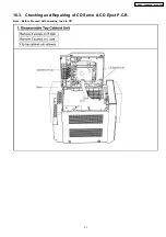
Page 29: ...10 Service Positions Note For description of the disassembly procedures see the Section 9 10 1 Checking and Repairing of Main P C B 29 SA PM4E SA PM4EB SA PM4EG ...

Page 30: ...10 2 Checking and Repairing of Transformer P C B 30 SA PM4E SA PM4EB SA PM4EG ...

Page 31: ...10 3 Checking and Repairing of CD Servo CD Eject P C B Note Before Proceed with checking load in CD 31 SA PM4E SA PM4EB SA PM4EG ...

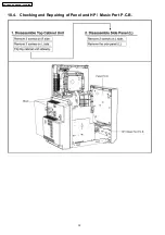
Page 32: ...10 4 Checking and Repairing of Panel and HP Music Port P C B 32 SA PM4E SA PM4EB SA PM4EG ...

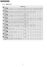
Page 33: ...0 1 6 1 6 0 0 1 9 1 9 0 1 7 1 7 STANDBY 0 0 0 0 0 0 0 0 0 0 0 0 0 0 0 0 0 0 0 0 Ref No MODE 41 42 43 44 45 46 47 48 49 50 51 52 53 54 55 56 57 58 59 60 CD PLAY 0 2 2 4 1 7 1 9 1 0 3 2 1 2 0 1 2 1 6 1 6 0 9 1 4 1 5 1 5 0 3 2 0 0 STANDBY 0 0 0 0 0 0 0 0 0 0 0 0 0 0 0 0 0 0 0 0 Ref No MODE 61 62 63 64 65 66 67 68 69 70 71 72 73 74 75 76 77 78 79 80 CD PLAY 3 2 0 0 0 0 0 3 3 3 2 9 0 3 2 0 1 6 0 1 6 3 ...

Page 34: ... 4 7 4 7 4 7 4 7 4 7 4 7 0 0 0 0 0 0 9 5 0 7 STANDBY 0 4 0 4 0 4 0 4 0 4 0 4 0 4 0 4 0 4 0 4 0 4 0 4 0 4 0 4 0 0 0 0 0 1 0 1 Ref No MODE 21 22 23 24 25 26 27 28 29 30 31 32 CD PLAY 4 8 0 0 4 8 4 8 0 4 8 4 7 4 8 4 7 4 8 4 8 STANDBY 0 2 0 2 0 2 0 2 0 2 0 0 0 0 0 0 0 Ref No MODE 1 2 3 4 5 6 7 8 9 10 11 12 13 14 15 16 CD PLAY 2 8 0 5 6 0 2 8 2 8 0 3 0 2 6 2 6 0 0 5 6 0 2 8 STANDBY 0 2 0 0 0 0 0 2 0 0 ...

Page 35: ...C B E C B E C B E C B CD PLAY 0 0 0 0 0 0 9 0 9 0 9 0 0 0 3 STANDBY 0 0 0 0 0 0 0 0 0 0 0 0 0 0 0 Ref No MODE E C B E C B E C B E C B E C B CD PLAY 3 2 3 3 2 4 0 0 0 0 0 0 7 7 9 8 4 6 5 9 7 1 STANDBY 0 0 0 0 0 0 0 0 0 0 0 0 0 3 0 3 0 Ref No MODE E C B E C B E C B E C B CD PLAY 3 15 4 5 0 3 2 0 0 1 5 0 1 0 1 5 0 1 STANDBY 4 7 17 6 4 6 0 3 2 0 0 1 8 0 0 1 8 0 SA PM4E EB EG MAIN P C B Q652 Q800 Q801 ...

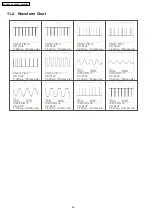
Page 36: ... p 50msec div CN451 PIN 3 CD PLAY 3 60Vp p 50msec div IC800 PIN 12 CD PLAY 4 16Vp p 50nsec div IC800 PIN 13 CD PLAY 2 64Vp p 50nsec div IC800 PIN 15 CD PLAY 1 72Vp p 10usec div IC800 PIN 16 CD PLAY 3 40Vp p 10usec div IC800 PIN 29 CD PLAY 3 40Vp p 10msec div IC800 PIN 33 CD PLAY 3 68Vp p 10msec div CN301 PIN 13 CD PLAY 3 44Vp p 10msec div 36 SA PM4E SA PM4EB SA PM4EG ...

Page 37: ...PbF 2 1 1615 CN7001 OPTICAL PICKUP M7301 TRV MOTOR M7302 SPL MOTOR PbF W400 SOLDER SIDE WH950 1 7 JK950 JK951 HEADPHONE MUSIC PORT SOLDER SIDE PbF 3 1 FL900 CN451 CN450 CN301 CP800 JK301 P1 SPEAKERS SENSOR VOLUME M M JW601 EXT ANT AM FM ANTENNA B MAIN P C B C PANEL P C B F TRANSFORMER P C B A CD SERVO P C B E CD EJECT P C B D HP MUSIC PORT P C B CAUTION RISK OF ELECTRIC SHOCK AC VOLTAGE LINE PLEAS...

Page 38: ...SA PM4E SA PM4EB SA PM4EG 38 ...

Page 39: ... 0 0 6482 52176 2 0 2 84 28 28 8 64 8 45 1614 52 0 1614 126 2 72 2 5 481 2 1 75 1 64 0 1 6 126 2 72 2 161 6 614 5 10 7 614 5 4 6 A 8 2 84 84 84 8 8 3 59 6 0 5 481 241 5514 6 5 0 241 5514 6 6 4 108 46 4 176 8 1 24 8 1 4 10 06 56 5 0 0 0 1764 5 0 4 0 0 0 0 0 0 0 0 0 0 5 2 5 481 126 2 72 70 6 1 4 61 0 1 4 61 0 1 4 4 5 6 59 6 SA PM4E SA PM4EB SA PM4EG 39 ...

Page 40: ...52A 6 52A 52A 6 670 4A 6 670 4A4 6 52A 5 5 8 76 81 A 1 81 A 1 4 6 A 5 A 6 A 2 106A 6 8 6 176 8 8 84 5 5 8 6 0 8 8KP 8UVFD 0 8 6 59 6 3 3 3 8 8 8 0 0 8 81 6 4 7 614 81 6 4 7 614 81 6 4 7 614 3 A 6 A56 6 A A12 0A59 4 56A59 456 A 3 8 8 5 4 4 8 59 6 15 2 2 15 41 2 62411 59 6 3 41 2 62411 59 6 3 2A8 61 52 3 82 81 6 4 7 614 176 8 5 5 8 855 8 84 6 6 59 6 3 59 6 3 6 6 0 2 6 2 0 0 0 0 0 0 0 0 2 0 0 0 0 0 0...

Page 41: ... 6 76 3 76 0 59 6 76 176A4 176A 0A 0A4 176A4 176A 6 4 6 4 9 0 9 0 9 0 8 9 0 9 0 8 2 2A8 3 8 59 6 61 5 481 1 4 52A 6 52A 670 4A 6 670 4A4 6 0 0 0 0 5 0 0 5 0 5 0 0 5 0 0 5 0 0 5 0 0 5 0 0 5 0 0 7 5 0 0 5 2 0 2 75 2146 1 4 61 0 1 4 61 0 1 4 61 0 1 4 75 2146 2 75 2146 2 0 2 52 45 8 8 8 3 3 SA PM4E SA PM4EB SA PM4EG 41 ...

Page 42: ...SA PM4E SA PM4EB SA PM4EG 42 ...

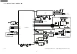
Page 43: ... safety Furthermore special parts which have purposes of fire retardant resistors high quality sound capacitors low noise resistors etc are used When replacing any of components be sure to use only manufacturer s specified parts shown in the parts list Capacitor values are in microfarad µF unless specified otherwise F Farad pF Pico Farad Resistance values are in ohm Ω unless specified otherwise 1K...

Page 44: ...44 SA PM4E SA PM4EB SA PM4EG ...

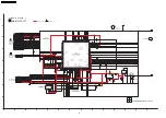
Page 45: ...2 11 10 2 4 6 8 9 7 5 3 1 13 14 15 16 CN7001 1 2 3 4 5 6 7 8 9 26 27 28 29 30 31 32 33 34 67 68 69 70 71 72 73 74 75 92 93 94 95 96 97 98 99 100 10 66 35 91 11 65 36 90 12 64 13 63 37 89 38 88 14 62 15 61 16 60 39 87 40 86 41 85 17 59 18 58 19 57 20 56 42 84 43 83 44 82 45 81 21 55 22 54 23 53 24 52 25 51 46 80 47 79 48 78 49 77 50 76 NTEST2 PRAMVDD15 PRAMVDD33 PC DQSYTXT SMCK PMCK NSRVMONON PD LD...

Page 46: ...1K 3 3K 10P 10K 22K 22K 22K 100P 100P 10K 100P 1000P 50V1 3 3K 50V47 50V1 22K 10K 16V0 018 16V0 018 4 7K 1000P 6 3V100 1000P 1 8K 4 7K 50V1 50V1 0 047 4 7K 0 047 16V10 100K 10K 47P 0 033 7P 0 1000P 0 01 0 047 100K 4 7K 0 022 1000P 10P 3 3K 1000P 7P 100K 0 0 01 68 TUNER IC 100K 15P 10K B0AACK000004 G0C101KA0029 H0A750200020 G2BPC0000017 J0B1075A0121 G2BAC0000055 Q1 B1ADBF000026 SWITCH B0CDAD000010 ...

Page 47: ... R205 C210 220P 220P C410 3 3K R211 3 3K R411 2 7K R202 C401 220P 2 7K R402 C201 220P 6 8K R204 6 8K R404 2 7K R203 C203 220P C463 16V100 50V0 33 C448 C429 0 01 C456 0 056 C462 0 039 C461 0 039 50V0 1 C443 C445 50V0 1 50V1 C233 C446 0 068 C444 0 068 R446 27K R447 27K C441 0 015 C442 0 015 C440 0 015 C449 0 015 50V1 C433 R403 2 7K 16V47 C325 R324 1K R321 2 2K 220 R323 X320 X320 H0H433400002 220P C4...

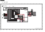
Page 48: ...03 6 5 8 9 11 12 10 14 15 13 7 2 1 4 3 17 17 1 1 17 16 CN301 CD_RST REST_SW Q303 B1ADCF000063 LOADING SWITCH Q303 STAT CD_MLD CD_MCLK 7 5V CD_MDATA BLKCK TOP_OPEN_SW GND 16V10 C816 470K R815 FL_CS D802 B0ACCK000005 MBP1 GND MBP2 D_MPUTX D_MPUCLK C801 16V100 2 1 3 IC801 C0CAABC00007 3 3V REGULATOR IC C800 VSS VIN VOUT 6 3V100 D803 B0BC4R600016 D804 B0BC01000014 R802 2 2K Q800 B1AAJC000019 VOLTAGE R...

Page 49: ...R IC C651 16V22 Q653 2SD1819A0L VCC DET SWITCH R654 27K R653 1K C658 25V3300 GND A9V 1 4 2 3 IC650 C0DAZYY00016 9V REGULATOR IC 7 5V VCC 3 3V D5V VCCDET FL3 3V 3 1 2 B0ADCJ000020 D652 PCONT1 1 2 IP800 K5G251A00008 0 25A GND1 VAC AMP_VCC1 PGND Vin Vstdby GND CD3 3V NC OUT VCC GND CTL VREF AGND DGND TGND VSS VIN VOUT W469 0 15 16 17 18 19 20 21 22 23 24 25 26 27 28 I J L M N P O K SCHEMATIC DIAGRAM ...

Page 50: ...ER ICSEG9 SEG11 SEG12 SEG10 GND2 SEG8 SEG5 SEG4 SEG3 SEG2 SEG1 SEG17 GRID11 GRID10 GRID9 GRID8 SEG7 SEG6 C909 50V22 R915 100K VP C903 0 1 R916 100K SEG14 SEG13 SEG16 SEG15 C905 0 1 6 8 9 7 2 1 4 5 3 10 11 CN900 GRID7 GRID6 GRID5 GRID4 GRID3 GRID2 GRID1 GND2 220P C912 GND2 C904 0 01 C910 6 3V470 BASS TREBLE CD MUSIC PORT FF A Vp SEG1 SEG17 SEG16 VDD SEG7 SEG10 SEG11 21 SEG9 22 SEG8 34 GRID9 35 GRID...

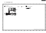
Page 51: ..._SW GND HP_R HP_L AUX_RCH AUX_LCH 1 2 W400 TOP_OPEN_SW GND S1000 CD EJECT A B C D E F G H 1 2 3 4 5 6 7 8 9 10 11 12 13 14 1 2 3 4 5 6 7 8 9 10 11 12 13 14 A B D E F H G C MAIN SIGNAL LINE SCHEMATIC DIAGRAM 7 SA PM4E EB EG HP MUSIC PORT CD EJECT CIRCUIT CD EJECT CIRCUIT TO MAIN CIRCUIT CN450 ON SCHEMATIC DIAGRAM 3 TO MAIN CIRCUIT CP800 ON SCHEMATIC DIAGRAM 4 HP MUSIC PORT CIRCUIT AUX SIGNAL LINE S...

Page 52: ...B0EAKM000117 D605 C605 50V100 D602 D604 D601 D604 B0EAMM000038 2 1 4 3 CN900B 1 3 2 CN650 14 12 13 15 9 10 7 8 11 2 3 1 4 6 5 F1 250V 630mA FL1 GND2 VP FL2 AMP_VCC1 VAC GND1 T601 G4CYAYY00142 MAIN TRANSFORMER A B C D E F G H 1 2 3 4 5 6 7 8 9 10 11 12 13 14 1 2 3 4 5 6 7 8 9 10 11 12 13 14 A B D E F H G C B SIGNAL LINE B SIGNAL LINE SCHEMATIC DIAGRAM 8 SA PM4E EB EG TRANSFORMER CIRCUIT TRANSFORMER...

Page 53: ...3 TP11 IC7001 R7335 R7325 C7315 R7315 R7323 C7338 R7331 C7352 R7328 R7330 R7339 C7216 C7161 C7244 R7211 C7217 C7204 W7012 W7015 W7013 R7212 W7014 C7102 C7142 C7107 C7234 W7011 C7155 C7154 W7021 W7016 W7017 W7022 W7018 W7019 W7020 C7626 C7164 C7165 W7005 W7024 W7023 R7111 C7264 R7336 C7339 R7349 TP24 R7332 W7002 W7010 W7009 W7008 W7007 W7006 W7004 W7003 W7001 C7243 C7670 C7253 TP1 TP3 TP4 TP31 TP7 ...

Page 54: ...3 R445 R411 C411 R401 C211 R201 C201 R402 R206 R205 R211 C465 C464 C213 C413 C210 C410 C401 R202 D802 R815 C821 R823 R824 C824 R818 R827 C851 R819 R820 C819 R862 R828 C850 C830 C829 C854 R829 C836 C835 C831 Q802 Q803 R866 R867 R868 R846 C848 R836 R847 R870 C847 C843 R842 D800 D801 C838 D803 R802 D804 C803 R838 R839 C853 R853 R837 R832 R833 R834 R844 R306 R302 R304 R848 R849 R843 R856 R854 R869 R85...

Page 55: ... W903 W904 C908 D901 W905 W906 IC900 R909 C903 C905 C913 C912 R908 C911 R910 R915 R916 R905 C904 D900 R912 R911 C900 C909 R904 R903 R901 R902 R900 C907 C906 R907 R913 R906 R914 R917 S904 MUSIC PORT S905 STOP DEMO VOLUME PbF W400 S1000 CD OPEN CLOSE 0123A 0123A JK951 WH950 JK950 C955 R955 C952 R952 C953 C950 R953 R950 L950 C954 C951 HEADPHONE MUSIC PORT 1 2 3 4 3 2 1 1 2 3 4 5 6 7 8 9 10 11 3 2 1 1...

Page 56: ...SA PM4E SA PM4EB SA PM4EG 56 ...

Page 57: ...25K M 16P AN17831A E C B C0CAABC00007 C0DAZYY00016 B1AAJC000019 2SB0621AHA B0AACK000004 B0BC5R600003 B0BC01000014 Cathode Ca A Anode B3AAA0000487 B0BC8R100004 B0BC6R700006 B0BC02900004 MAZ80560ML B0ADCJ000020 B0EAKM000117 B0EAMM000038 B0CDAB000019 B0CDAD000010 B0ACEL000004 Ca Cathode Anode A B0ACCK000005 B C E E C B Cathode Ca A Anode 1 3 4 5 2 1 12 1 2 3 12 34 A Ca Anode Cathode Anode Anode Catho...

Page 58: ...ut 50 ARFFB I ARF Feedback Signal I P 51 ARFIN I Audio RF Signal I P 52 DSLF I Loop Filter Terminal For DSL Pin No Mark I O Function 53 IREF I Reference I P 54 PLLF PLL Loop Filter Terminal Phase Compare 55 PLLF0 PLL Loop Filter Terminal Speed Compare 56 OUTL O Audio O P LCH 57 AVSS1 GND 58 AVDD1 Analog Power Supply Voltage 1 59 OUTR O Audio O P RCH 60 DVSS3 GND3 Digital Circuit 61 NSRVMONON I Ser...

Page 59: ...LSI Command Load 36 N C No Connection 37 1 8V Power Supply 1 8V 38 MUTEA O Analog MUTE Output L MUTE ON Pin No Mark I O Function 15 D3 O Motor Drive 3 reverse action output 16 D3 O Motor Drive 3 forward action output 17 D4 O Motor Drive 4 reverse action output 18 D4 O Motor Drive 4 forward action output 19 PVCC2 Power Supply 2 for Driver 20 PGND2 Ground Connection 2 for Driver 21 24 N C No Connect...

Page 60: ...ner 87 N C No Connection 88 N C No Connection 89 VDD Micom VDD 5V 90 N C No Connection 91 VSS Ground Connection 92 KEY1 I Key 1 Input 93 KEY2 I Key 2 Input 94 N C No Connection 95 N C No Connection 96 DCDET I DC Level Detection Input 97 REGION I Region Setting Input 98 N C No Connection 99 N C No Connection 100 VREF A D Converter reference voltage 3 3V 60 SA PM4E SA PM4EB SA PM4EG ...

Page 61: ...19 Exploded Views 19 1 Cabinet Parts Location Traverse Part Location SA PM4E SA PM4EB SA PM4EG 61 ...

Page 62: ...19 2 Packaging SA PM4E SA PM4EB SA PM4EG 62 ...

Page 63: ...IC651 C0DBZGC00067 IC 3 3V REGULATOR M IC652 C0CAABC00007 IC 3 3V REGULATOR M IC700 C0ABBB000297 IC DUAL OP AMP M IC800 MN101EF16ZXW IC MICROPROCESSOR M IC801 C0CAABC00007 IC 3 3V REGULATOR M 20 Replacement Parts List Important safety notice Components identified by mark have special characteristics important for safety Furthermore special parts which have purposes of fire retardent resistors high...

Page 64: ... JOG M SWITCHES S900 EVQ21405RJ SW POWER M S901 EVQ21405RJ SW BASS TREBLE M S902 EVQ21405RJ SW FF M S903 EVQ21405RJ SW REW M S904 EVQ21405RJ SW MUSIC PORT M S905 EVQ21405RJ SW STOP DEMO M S906 EVQ21405RJ SW TUNER M S907 EVQ21405RJ SW CD M S1000 RSP1A026 Q SW CD EJECT M Ref No Part No Part Name Description Remarks S7201 RSH1A048 A SW RESET M CONNECTORS CN301 K1MN17A00040 17P FFC CONNECTOR M CN450 K...

Page 65: ... Sp Po Cz Ru Ur M E Ref No Part No Part Name Description Remarks A3 RQTV0211 B O I BOOK En M EB E A4 N1DADYY00003 AM ANTENNA M RESISTORS R1 ERJ3GEYJ103V 10K 1 16W M R2 ERJ3GEY0R00V 0 1 16W M R3 D0GB332JA007 3 3K 1 16W M R4 D0GB104JA007 100K 1 16W M R5 ERJ3GEYJ680V 68 1 16W M R6 D0GB104JA007 100K 1 16W M R7 D0GB104JA007 100K 1 16W M R8 D0GB103JA007 10K 1 16W M R9 ERJ3GEY0R00V 0 1 16W M R10 D0GB104J...

Page 66: ...1K 1 16W M R837 D0GB223JA041 22K 1 16W M R838 D0GB101JA007 100 1 16W M R839 ERJ3GEYJ102V 1K 1 16W M Ref No Part No Part Name Description Remarks R840 D0GB101JA007 100 1 16W M R842 D0GB472JA041 4 7K 1 16W M R843 D0GB472JA041 4 7K 1 16W M R844 ERJ3GEYJ102V 1K 1 16W M R846 D0GB101JA007 100 1 16W M R847 D0GB101JA007 100 1 16W M R848 ERJ3GEYJ102V 1K 1 16W M R849 ERJ3GEYJ102V 1K 1 16W M R850 ERJ3GEYJ102...

Page 67: ...471A219 470P 50V M C322 F2A1C470A016 47P 16V M Ref No Part No Part Name Description Remarks C323 ECJ1VB1H561K 560P 50V M C324 ECJ1VC1H102J 1000P 50V M C325 F2A1C470A016 47P 16V M C326 F1H1H470A230 47P 50V M C327 F1H1H470A230 47P 50V M C333 ECQV1H224JL3 0 22 50V M C351 ECJ1VC1H471J 470P 50V M C352 F1H1H102A219 1000P 50V M C364 ECQV1H224JL3 0 22 50V M C365 ECQV1H224JL3 0 22 50V M C369 ECQV1H224JL3 0...

Page 68: ...48 220P 50V M C913 F1H1H221A748 220P 50V M C950 F1H1H102A219 1000P 50V M C951 F1H1H472A219 4700P 50V M C952 ECJ1VB1H103K 0 01 50V M C953 F1H1H102A219 1000P 50V M C954 F1H1H472A219 4700P 50V M C955 ECJ1VB1H103K 0 01 50V M C7102 ECJ1VB1A474K 0 47 10V M C7107 ECJ1VB1H223K 0 022 50V M C7142 F1H1H332A013 3300P 50V M C7154 F1H1C104A041 0 1 16V M C7155 F1H1C104A041 0 1 16V M C7161 F1H1C104A041 0 1 16V M ...

Reviews: