50
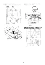
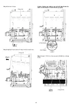
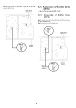
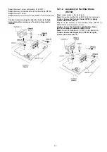
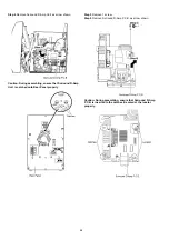
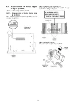
9.17.1.
Assembly of Audio Digital Amp IC
(IC5200)
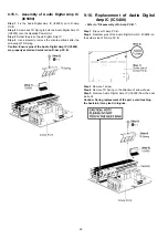
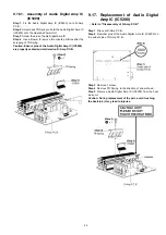
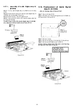
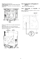
Step 1 Fix the Audio Digital Amp IC (IC5200) on to D-Amp
P.C.B..
Step 2 Screw back TR Spring to hold the Audio Digital Amp IC
(IC5200) onto the Heatsink Power Unit.
Step 3 Solder the pins of Audio Digital Amp IC.
Step 4 Use a blower to remove the minute particles after the
screwing of TR Spring.
Caution: Ensure pins of the Audio Digital Amp IC (IC5200)
are properly seated and soldered on D-Amp P.C.B..
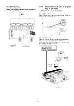
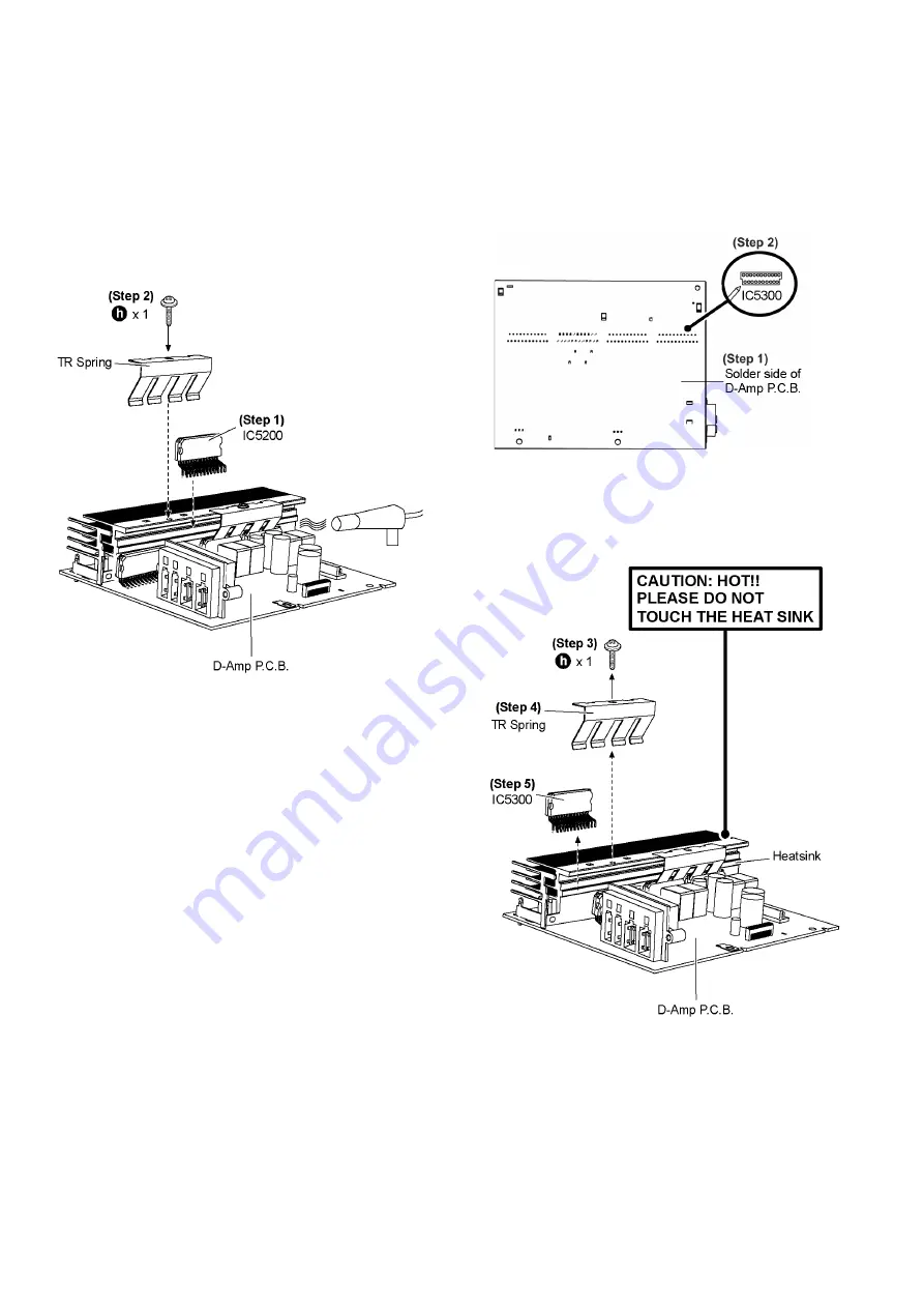
9.18. Replacement of Audio Digital
Amp IC (IC5300)
• Refer to “Disassembly of D-Amp P.C.B.”.
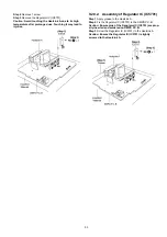
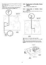
Step 1 Flip over D-Amp P.C.B..
Step 2 Desolder pins of the Audio Digital Amp IC (IC5300) on
the solder side of D-Amp P.C.B..
Step 3 Remove 1 screw.
Step 4 Remove TR Spring in the direction of arrow shown.
Step 5 Remove Audio Digital Amp IC (IC5300).
Caution: During replacement of the part, avoid touching
the heatsink, it may lead to injuries.
Summary of Contents for SA-AKX92PH
Page 13: ...13 5 Location of Controls and Components 5 1 Main Unit Key Button Operation ...
Page 14: ...14 5 2 Remote Control Key Button Operation ...
Page 15: ...15 5 3 Media Information ...
Page 27: ...27 7 2 4 Surround D Amp P C B Fig 4 Surround D Amp P C B Audio Digital Amp IC IC5900 ...
Page 33: ...33 9 2 Main Components and P C B Locations ...
Page 73: ...73 Step 9 Ground the 24P FFC with a short pin ...
Page 92: ...92 ...
Page 93: ...93 14 Simplified Block Diagram 14 1 Overall Simplified Block Diagram ...
Page 104: ...104 ...
Page 140: ...140 ...
Page 157: ...157 MMH1103 ...

