background image

Replacement

64

 - ENGLISH

Maintenance

Attaching the Lens Cap

When moving this projector or while not using it over an extended period of time, attach the lens cap.

Attach the lens cap according to the following procedures.

Thread the string (supplied) through  

1 ) 

the hole on the lens cap.
Push the other end of the string into  

2 ) 

the front part of the hook (as the  

picture shown) on the bottom of the 

projector.

Summary of Contents for PT-VX400

Page 1: ...purchasing this Panasonic Product Before operating this product please read the instructions carefully and save this manual J J for future use For information on using the product via a network refer...

Page 2: ...nued compliance follow the attached installation instructions which includes using the provided power cord and shielded interface cables when connecting to computer or peripheral device If you use ser...

Page 3: ...ust Failure to observe this will cause a fire If dust builds up on the power plug the resulting humidity can damage the insulation z z If not using the projector for an extended period of time pull th...

Page 4: ...hands directly into this light z z Be especially careful not to let young children look into the lens In addition turn off the power and z z disconnect the power plug when you are away from the proje...

Page 5: ...ase do not rub your eyes Rinse with clean water and seek medical advice immediately Do not disassemble the lamp unit If the lamp breaks it could cause injury Lamp replacement The lamp has high interna...

Page 6: ...ntilate the room immediately Do not touch or bring your face close to the broken pieces Failure to observe this will cause the user to absorb the gas which was released when the lamp broke and which c...

Page 7: ...dio The digital zoom function allows you to focus on the crucial information during a presentation The MIC function and 10W audio output allows you to make a presentation without any external audio eq...

Page 8: ...n the Projector 26 Enter a PIN code 27 PIN code Protection 27 Turning Off the Projector 28 Projecting 29 Selecting the image 29 How to adjust the state of the image 29 Basic operations by using the re...

Page 9: ...kground 51 Display 51 Logo 51 HDMI setup 52 Terminal 52 P IN P PT VW330E Only 52 Power management 53 Direct on 53 Standby mode 53 P timer 54 Closed caption 54 Lamp power 55 Remote control 55 Security...

Page 10: ...erature changes greatly z z Operating environment page 77 Doing so may shorten the life of the lamp or result in deformation of the outer case and malfunctions Near high voltage power lines or near mo...

Page 11: ...horized operation of this product by a malicious third party z z Interfering or stopping of this product by a malicious third party z z Security instruction J J page 55 Make your password as difficult...

Page 12: ...all white screen in the test pattern for an hour or more Optical components J J Operating the projector in an environment with high temperature or heavy exposure to dust or tobacco smoke will reduce...

Page 13: ...control unit RGB signal cable x1 6103580425 Filter cover x1 6103568881 AC power cord holder x1 6103573700 6103573694 Lens cap x1 6103545790 String x1 6103430249 PIN Code Label x1 Soft Carrying Case x1...

Page 14: ...or Monitoring Control Software 2 6 Logo Transfer Software 2 0 Windows This software allows you to create original images such as company logos to be displayed when projection starts and transfer them...

Page 15: ...15 P IN P Button Only for PT VW330E Operate the Picture In Picture function page 33 16 IMAGE Button Select the image mode page 33 17 MUTE Button Mute the sound page 33 18 Remote control signal emitter...

Page 16: ...the exhaust vent Do not put heat sensitive objects near this side 9 Speaker 10 AC IN 11 Terminals page 17 12 Air intake port Air filter cover page 60 13 Adjustable feet Adjusts the projection angle W...

Page 17: ...ts to the audio input signals AUDIO IN has right and left L and R terminals 10 VIDEO IN Connects to VIDEO input signals 11 COMPUTER AUDIO IN 1 Connects to the audio input signals 12 COMPUTER AUDIO IN...

Page 18: ...the initial ID number is ALL J J Setting the ID number 1 While holding down the MENU button press the IMAGE button The number of times you press the IMAGE button corresponds to the desired ID code nu...

Page 19: ...tor installed vertically or tilted right or left Use under such conditions could result in equipment z z damage The projector must be installed so that its inclination to the horizontal plane is 40 or...

Page 20: ...6 1 3 m 4 10 2 0 m 6 69 1 52 m 60 1 7 m 5 61 2 8 m 9 12 1 6 m 5 09 2 5 m 8 27 1 5 m 4 95 2 5 m 8 04 1 78 m 70 2 0 m 6 56 3 3 m 10 66 1 8m 5 94 3 0 m 9 68 1 8 m 5 77 2 9 m 9 42 2 03 m 80 2 3 m 7 51 3 7...

Page 21: ...4 m 11 06 2 29 m 90 2 2 m 7 05 3 5 m 11 42 2 3 m 7 68 3 8 m 12 47 2 54 m 100 2 4 m 7 84 3 9 m 12 73 2 6 m 8 53 4 2 m 13 88 3 05 m 120 2 9 m 9 42 4 7 m 15 29 3 1 m 10 27 5 1 m 16 67 3 81 m 150 3 6 m 1...

Page 22: ...You can turn them in the opposite direction to contract them You can adjust the projection angle vertically Attention Heated air comes out of the air exhaust port while the lamp is lit Do not touch t...

Page 23: ...o signals the projector supports see List of compatible signals z z page 72 Connecting example Attention When connecting with a video deck be sure to use the one with a built in time base corrector TB...

Page 24: ...he power cord holder correctly as Picture 1 shown Attaching J J Attach the AC power cord with the power cord clamp to the projector by following these steps Plug the power cord with the power cord hol...

Page 25: ...plugged The projector is in stand by mode after the cooling is completed Flashing The projector cannot be turned on until the normal power off processing for fan cooling is completing and the POWER i...

Page 26: ...layed on the screen please move the pointer to input source desired by pressing the and the SELECT button And then follow the input signal guidance window to correct the signal and connection If the p...

Page 27: ...T button so that you can start to operate the projector If you entered an incorrect PIN code PIN code and the number will turn red for a moment Enter the correct PIN code all over again Note If the PI...

Page 28: ...rtened when the normal power off processing for fan cooling is completed compared with the time the AC power cord is immediately unplugged after the power off J J Direct Power Off function Even if you...

Page 29: ...at that is suitable for the input signal in Component or RGB in the Input menu page 37 Check the aspect ratio of the screen and the image and z z select the optimum aspect ratio under the Screen menu...

Page 30: ...to Computer 1 RGB Computer 1 Scart Computer 1 Component input COMPUTER 2 Switches to Computer 2 RGB input HDMI Switches to HDMI input VIDEO Switches to Video input S VIDEO Switches to S video input C...

Page 31: ...rection z z If you press the KEYSTONE button on the remote z z control once more while the keystone dialog box is being displayed the keystone adjustment will be canceled page 47 The adjustable range...

Page 32: ...rate the Count up Count down function button Press P TIMER button on the remote control Note To stop the count time press the P TIMER button z z To cancel the P timer function press and hold the P TIM...

Page 33: ...ote For details see Image select of Main menu z z page 42 Using the P IN P button PT VW330E Only This function allows you to operate the Picture In Picture function button Press P IN P button on the r...

Page 34: ...ss or the SELECT button 3333 The submenu appears so that you can select the sub menu item Press to select the desired sub 4444 menu item Press the SELECT button or press 5555 to enter the desired item...

Page 35: ...enu item Factory default Page Computer 1 RGB 37 Computer 2 RGB 37 HDMI 37 Video 37 S video 37 PC adjust J J Sub menu item Factory default Page AUTO PC adj 39 Fine sync 40 Total dots 40 Horizontal 40 V...

Page 36: ...u item Factory default Page Volume 32 49 Mute Off 49 MIC Off 49 MIC gain 32 49 Standby MIC out Off 49 Setting J J Sub menu item Factory default Page Language English 50 Menu position Center 50 Auto se...

Page 37: ...nal conforming to the provided PC Systems Auto is displayed on the System Menu box and the Auto PC adjustment function works to display proper images If the image is not projected properly a manual ad...

Page 38: ...its performance COMPONENT VIDEO SIGNAL FORMAT If the projector cannot reproduce proper video image select a specific component video signal format among 480i 576i 480p 576p 720p 1035i and 1080i Press...

Page 39: ...re adjustment parameters The adjusted parameters from the Auto PC adjustment can be stored in the projector Once the parameters are stored the setting can be done just by selecting a Mode 1 10 in the...

Page 40: ...adjustment dialog box Press to adjust the value 3333 The value can be adjusted from 0 to 31 z z Total dots Press to select Total dots 1111 Press the SELECT button to display 2222 the adjustment dialog...

Page 41: ...projector Display area V Press to select Display area V 1111 Press the SELECT button to display 2222 the dialog box Press to adjust the vertical area 3333 displayed by this projector Reset To reset th...

Page 42: ...image projected on a blackboard Press to select Blackboard Green and then press the SELECT button This mode helps enhance the image projected z z on a blackboard This is mainly effective on a green c...

Page 43: ...isplay 2222 the adjustment dialog box Press to adjust the setting value 3333 Operation Adjustment Adjustment range Press increase the intensity of the color Maximum value 63 Press decrease the intensi...

Page 44: ...s Press to select Sharpness 1111 Press the SELECT button to display 2222 the adjustment dialog box Press to adjust the setting value 3333 Operation Adjustment Adjustment range Press increase the sharp...

Page 45: ...ed Off Disabled L1 For an active picture L2 For a still picture Film For watching a film Note When input video signal to the projector Progressive z z will become available Reset To reset the adjusted...

Page 46: ...el size 1280 x 800 the projector enters to the panning mode automatically Press to select True and then 1111 press the SELECT button Press to pan the image 2222 When adjusted the arrows will turn red...

Page 47: ...he On Screen Menu disappears and z z D zoom appears Press the SELECT button to zoom 2222 out image size The projected image can be also compressed z z by pressing the D ZOOM or the SELECT button To ex...

Page 48: ...used to project the image to a 4 3 or 16 9 projection screen Press to select Screen aspect 1111 and then press the SELECT button Press to choose one from the 2222 items as below Default 16 10 16 10 is...

Page 49: ...LUME buttons MIC Press to select MIC and then 1111 Press the SELECT button Press to switch the MIC function 2222 On Off When Off is selected in MIC function the MIC z z gain and Standby MIC out functi...

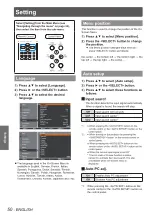
Page 50: ...ght the top left the top right the center Auto setup Press to select Auto setup 1111 Press or the SELECT button 2222 Press to select these functions as 3333 follows J J Input search This function dete...

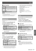
Page 51: ...this function when you want to project images after the lamp becomes bright enough The factory default setting is in this option Use this function when you want to project the image as early as possib...

Page 52: ...ONITOR OUT terminal on the back of the projector is switchable for computer 2 input or monitor output Press to select Terminal and 1111 then press the SELECT button Press to switch the item 2222 Compu...

Page 53: ...urned on if the input signal is reconnected or any button on the control panel or remote control is pressed Shut down When the lamp has been fully cooled down the power will be turned off Off Power ma...

Page 54: ...op on the screen menu then the indication changes into Restart Press the SELECT button at Restart to resume Count up or Count down Press the SELECT button at Reset to return to the following value Cou...

Page 55: ...to fit the code on the projector If the batteries are removed from the remote control for a z z long period of time the remote control code will be reset Security This function allows you to use the...

Page 56: ...On 1 mode 3 Set this function to Off when using the projector in non high altitude environment Select this mode when using the projector in high altitudes about 1 200 meters or more above the sea leve...

Page 57: ...ted CO2 Total power savings Reset appears Select z z Yes to continue Another confirmation dialog box appears select Yes to reset the Total power savings Warning log This function records anomalous ope...

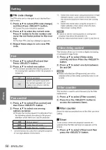
Page 58: ...o signal V sync freq J J The selected V sync freq is displayed The vertical frequency of the input signal is displayed in Hz or Hz when no signal Numbers of Hz doubles when during Interlace Screen J J...

Page 59: ...inside the projector is abnormally high The projector cannot be turned on And the POWER indicator also blinks in red Check Unplug the AC power cord and plug it again to turn on the projector Did you p...

Page 60: ...has an abrasive surface or a cloth that is moist oily or covered with dust z z Do not use excessive force when wiping the lens as it is fragile z z Attention The lens is made of glass Impacts or exces...

Page 61: ...Do not put anything into the air vents Doing so may result in malfunction of the projector z z Do not wash the filters with water or any other liquid matter Otherwise the filters may be damaged z z At...

Page 62: ...ed If pieces of glass get into your eyes or mouth seek medical advice immediately The lamp contains mercury Consult your local municipality or your dealer about correct disposal of used z z lamp units...

Page 63: ...xing screw and remove the lamp cover Remove the lamp cover by pulling it slowly toward z z the direction of the arrow Use a Phillips screwdriver to loosen the 3333 three lamp unit fixing screws until...

Page 64: ...g it over an extended period of time attach the lens cap Attach the lens cap according to the following procedures Thread the string supplied through 1111 the hole on the lens cap Push the other end o...

Page 65: ...z z adjusted correctly RGB cable is damaged z z No sound from the internal speaker The input terminals may not have been correctly connected z z 23 The volume may have been set to the minimum level z...

Page 66: ...z z 72 75 No sound is output from a HDMI device Set the sound channel of the attached device to Linear PCM z z If no audio signal is output during HDMI cable connection connect the z z audio cable to...

Page 67: ...Sub 9 pin male Outside view Pin No Signal name Contents NC RXD Received data TXD Transmitted data NC GND Earth NC NC NC NC J J Communication conditions Signal level RS 232C compliant Character length...

Page 68: ...colon is not necessary J J Basic format with sub command STX C1 C2 C3 ETX S1 S2 S3 S4 S5 E P1 P2 P3 P4 P5 P6 When transmitting a command which does not need a parameter the operation E and parameter a...

Page 69: ...Power ON POF Power OFF IIS INPUT selection Parameter VID Video SVD S video RG1 Computer 1 RGB RG2 Computer 2 RGB HD1 HDMI SCT Computer 1 Scart OSH AV mute function Turning off the projection and sound...

Page 70: ...HD SYNC VD DDC clock Pin assignments and signal names of COMPUTER IN 2 MONITOR OUT J J terminal Outside view Pin No Signal names Not assigned GND terminals R PR G G SYNC Y B PB HD SYNC VD Pin assignme...

Page 71: ...the Main Sub picture Display resolution is lowered when Inputting PC analog signals Between 100 140 MHz Images are not displayed and mark appears when Inputting PC analog signals More than 140 MHz In...

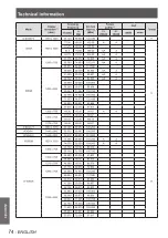
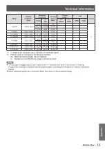
Page 72: ...0 31 50 A A 43 269 85 00 36 00 A A 640 x 400 31 47 70 09 25 175 A A 720 x 400 31 47 70 09 28 322 A A SVGA 800 x 600 35 156 56 25 36 00 A A 37 88 60 32 40 00 A A 46 875 75 00 49 50 A A 53 674 85 06 56...

Page 73: ...108 00 A A 1280 x 1024 62 50 58 60 108 00 A A 63 90 60 00 107 35 A A 63 34 59 98 108 18 A A 63 74 60 01 109 497 A A 71 69 67 19 117 004 A A 81 13 76 107 135 008 A A 63 98 60 02 108 00 A A 79 976 75 0...

Page 74: ...1 553 84 879 122 498 55 993 69 991 94 964 57 675 72 004 97 817 1366 x 768 48 36 60 00 86 67 A A 1360 x 768 47 70 60 00 86 67 56 16 72 00 100 19 1376 x 768 48 36 60 00 86 67 WSXGA 1 1680 x 1050 65 290...

Page 75: ...WXGA 1 1440 x 900 55 935 59 887 106 500 D WSXGA 1 1680 x 1050 65 290 59 954 146 250 D WUXGA 2 1920 x 1200 74 038 59 950 154 000 i added to the resolution value indicates an interlaced signal Picture q...

Page 76: ...0 60p Horizontal 45 kHz Vertical 60 Hz 1125 1080 60i Horizontal 33 75 kHz Vertical 60 Hz 625i 576i Horizontal 15 63 kHz Vertical 50 Hz 625p 576p Horizontal 31 25 kHz Vertical 50 Hz 750 720 50p Horizon...

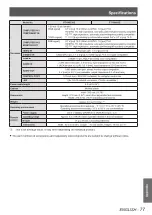
Page 77: ...0 5 V rms input impedance 22 k and more AUDIO OUT 1 M3 stereo mini jack stereo monitor output compatible 0 V rms to 2 0 V rms valuable output impedance 2 2 k and less CONTROL PORT 1 D sub 9 pin RS 232...

Page 78: ...l conditions Remove an unused ceiling mount bracket promptly z z Ensure to use a torque driver and do not use an electrical screwdriver or an impact screwdriver z z For details see the work instructio...

Page 79: ...indicator 59 Lamp unit 62 Language 50 List of compatible signals 72 Logo 51 M Main menu 35 Maintenance 60 Managing the indicated problems 59 Manual PC adjust 40 Menu Navigation 34 Menu position 50 MI...

Page 80: ...information about collection and recycling of old products and batteries please contact your local municipality your waste disposal service or the point of sale where you purchased the items Penaltie...

Reviews: