Chapter 2
Getting Started — Connecting
ENGLISH - 61
f
Directly connect the projector with the external device that will output the signal without going through a distributor, etc., when inputting quad
link signals. A phase difference is generated between the signals of Link 1, Link 2, Link 3, and Link 4, and the image may not be projected
correctly.
f
An error in signal detection may occur when an unsteady signal is input to the projector. In such case, set the [DISPLAY OPTION] menu
→
[SLOT IN] to the content corresponding to the input signal.
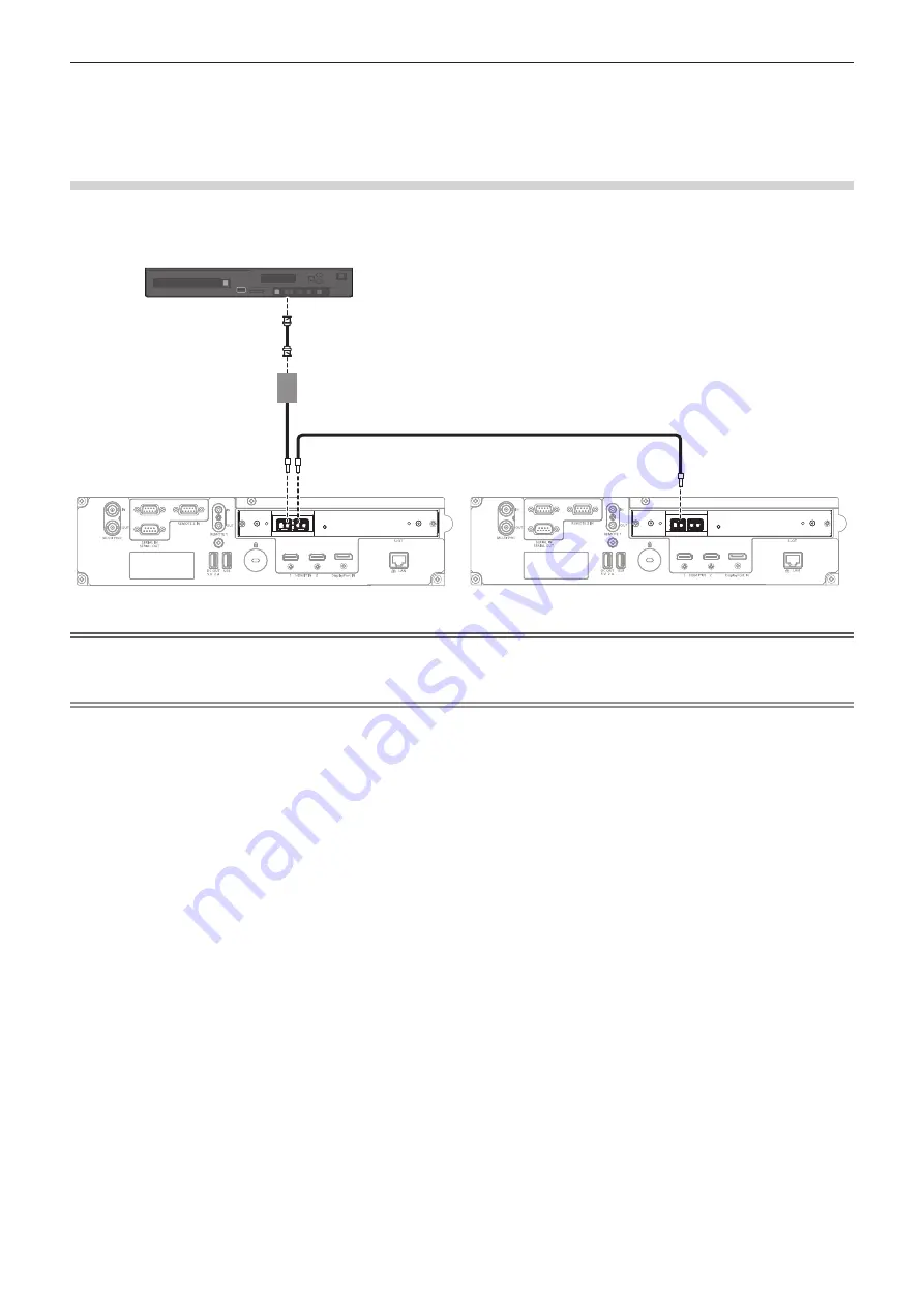
For <SDI OPT 1 IN> / <SDI OPT 2 IN> / <SDI OPT OUT> terminals of the Function Board
This is an example when the optional Function Board for 12G-SDI Optical (Model No.: TY-SB01FB) is installed in
<SLOT>.
TY-SB01FB
SIGNAL
SDI OPT
12G/3G/HD
1 IN
2 IN
OUT
TY-SB01FB
SIGNAL
SDI OPT
12G/3G/HD
1 IN
2 IN
OUT
Attention
f
The SFP module to be installed on this product is a Class 1 laser product. Do not look into the SFP module or the connector of the optical
fiber cable with the power of the projector turned on. Your eyes may be damaged when the laser goes into your eyes.
Note
f
Prepare the commercially available SFP module and the optical fiber cable required for connection according to the usage, video signal to
be input, specification of the external device to be connected, etc.
f
The transmission distance may become shorter and the image may not display correctly when there is dust on the connector of the SFP
module or optical fiber cable, or it is dirty. Attach the protection cap or cover supplied by each product to the connector of the SFP module or
the optical fiber cable if the optical fiber cable is not connected.
12G-SDI signal output compatible device
HD-SDI signal, 3G-SDI signal, 12G-SDI signal
SDI - optical converter
Optical fiber cable


