background image

About your projector

ENGLISH - 21

Preparation

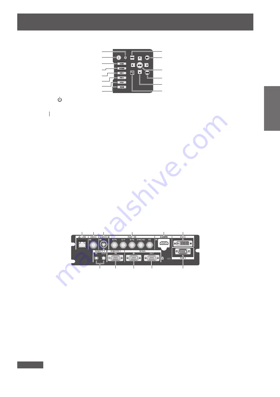
Control panel

(9)
(10)

(11)
(12)
(13)
(14)

(1)
(2)
(3)
(4)
(5)

(6)

(7)

(8)

(1) Power standby < > button

Sets the projector to the standby mode when the <MAIN 

POWER> switch on the projector is set to <ON>.

(2) Power on < > button

Starts projection when the <MAIN POWER> switch on the 

projector is set to <ON> when the power is switched off 

(standby mode).

(3) <VIDEO> button

Switches to VIDEO input.

(4) <S-VIDEO> button

Switches to S-VIDEO input.

(5) <RGB1> button

Switches to RGB1 input.

(6) <RGB2> button

Switches to RGB2 input.

(7) <DVI-D> button

Switches to DVI-D input.

(8) <HDMI> button

Switches to HDMI input.

(9) <MENU> button

Displays and erases the main menu.

Returns to the previous screen when a sub-menu is 

displayed.(

 page 44)

If you press the <MENU> button on the control panel for 

at least three seconds while the on-screen indication is off, 

the on-screen display is turned on.

(10) <LENS> button

Adjusts the focus, zoom, and shift (position) of the lens.

(11) <ENTER> button

Determines and executes an item in the menu screen.

(12) <SHUTTER> button

Use to temporarily turn off the image.(

 page 41)

(13)

▲▼◀▶

 selection buttons

Use to select items in the menu screen, change settings, 

and adjust levels.

It is also used to enter [SECURITY] passwords.

(14) <AUTO SETUP> button

Automatically adjusts the image display position while 

projecting the image.

[PROGRESS] is displayed on the screen while the image 

is adjusted automatically.(

 page 42)

Connecting terminals

(1)

(2) (3)

(4)

(5)

(6)

(7)

(8)

(9)

(10)

(11)

(1) <LAN> terminal

This is a terminal to connect to the network.

Used for control and monitoring. Image input through 

network connections is not possible.

(2) <VIDEO IN> terminal

This is a terminal to input video signals.

(3) <S-VIDEO IN> terminal

This is a terminal to input S video signals.

(4) <RGB 1 IN> (<R/P

R

>, <G/Y>, <B/P

B

>, <SYNC/HD>, 

<VD>) terminal

This is a terminal to input RGB signals or YC

B

C

R

/YP

B

P

R


signals.

(5) <HDMI IN> terminal

This is a terminal to input HDMI signals.

(6) <DVI-D IN> terminal

This is a terminal to input DVI-D signals.

(7) <REMOTE 1 IN> terminal / <REMOTE 1 OUT> terminal

These are the terminals to connect the remote control for 

serial control when the system uses multiple projectors.

(8) <REMOTE 2 IN> terminal

This is a terminal to remotely control the projector using 

the external control circuit.

(9) <SERIAL IN> terminal

This is a RS-232C compatible terminal to externally control 

the projector by connecting a computer.

(10) <SERIAL OUT> terminal

This is a terminal to output the signal connected to the 

serial input terminal.

(11) <RGB 2 IN> terminal

This is a terminal to input RGB signals or YC

B

C

R

/YP

B

P

R


signals.

Attention


z

When a LAN cable is directly connected to the projector, the network connection must be made indoors.

Summary of Contents for PT-DZ770E

Page 1: ...s sold separately K Black model the standard zoom lens supplied LK Black model the lens sold separately Before operating this product please read the instructions carefully and save this manual for future use Before using your projector be sure to read Read this first pages 2 to 8 Model No PT DZ770E PT DZ770EL TQBJ0443 DLPTM Projector Commercial Use Operating Instructions Functional Manual ENGLISH...

Page 2: ... mains plug This plug will only fit an earthing type mains socket This is a safety feature If you are unable to insert the plug into the mains socket contact an electrician Do not defeat the purpose of the earthing plug WARNING This is a class A product In a domestic environment this product may cause radio interference in which case the user may be required to take adequate measures CAUTION To as...

Page 3: ...f severe electrical shock if the cut off plug is inserted into any 13 amp socket If a new plug is to be fitted please observe the wiring code as shown below If in any doubt please consult a qualified electrician WARNING THIS APPLIANCE MUST BE EARTHED IMPORTANT The wires in this mains lead are coloured in accordance with the following code Green and Yellow Earth Blue Neutral Brown Live As the colou...

Page 4: ...h are coming loose from the wall Do not use anything other than the provided power cord Failure to observe this will result in fire or electric shocks Please note that if you do not use the provided power cord to ground the device on the side of the outlet this may result in electric shocks Clean the power plug regularly to prevent it from becoming covered in dust Failure to observe this will caus...

Page 5: ...ages can cause fire or electric shocks z z For any inspection adjustment and repair work please contact an Authorized Service Center Do not project an image with the lens cover attached Doing so can cause fire Do not allow metal objects flammable objects or liquids to enter inside of the projector Do not allow the projector to get wet Doing so may cause short circuits or overheating and result in ...

Page 6: ...advice immediately Do not disassemble the lamp unit Doing so can cause electric shocks burns or injury Lamp replacement The lamp has high internal pressure If improperly handled an explosion and severe injury or accidents will result z z The lamp can easily explode if struck against hard objects or dropped z z Before replacing the lamp be sure to turn the power off and to disconnect the power plug...

Page 7: ...rojector with cables still attached can damage the cables which will cause fire or electric shocks to occur ACCESSORIES Do not use the old lamp unit If used it could cause lamp explosion If the lamp has broken ventilate the room immediately Do not touch or bring your face close to the broken pieces Failure to observe this will cause the user to absorb the gas which was released when the lamp broke...

Page 8: ...V are trademarks of Crestron Electronics Inc The font used in the on screen displays is a Ricoh bitmap font which is manufactured and sold by Ricoh Company Ltd Adobe Flash Player is either a trademark or registered trademark of Adobe Systems Incorporated in the United States and or other countries Other names company names or product names used in these operating instructions are the trademarks or...

Page 9: ...e page 39 1 These are the steps to be taken when you switch on the power for the first time after purchasing the projector Features of the Projector Features of the Projector The unique optical system and lamp drive system achieve a high luminance and high color reproducibility Extensive lineup of optional lenses allow more flexible setup of the projector The long life filter reduces the maintenan...

Page 10: ... Making adjustments and selections 37 Switching off the projector 38 Direct power off function 38 Projecting 39 Selecting the input signal 39 Adjusting the focus zoom and shift 39 Moving the lens to the home position 40 Adjustment range by the lens position shift optical shift 40 Remote control operation 41 Using the shutter function 41 Using the on screen display function 41 Switching the input s...

Page 11: ...gistered data 76 Deleting a registered data 76 Protecting the registered data 77 Expanding signal lock in range 77 Managing the sub memory list 78 SECURITY menu 79 SECURITY PASSWORD 79 SECURITY PASSWORD CHANGE 79 DISPLAY SETTING 79 TEXT CHANGE 80 MENU LOCK 80 MENU LOCK PASSWORD 80 CONTROL DEVICE SETUP 80 NETWORK menu 82 NETWORK SETUP 82 NETWORK CONTROL 82 NETWORK STATUS 82 Network connections 83 A...

Page 12: ...e outer case and malfunctions z z Near high voltage power lines or near motors Doing so may interfere with the operation of the projector z z Place where there is high power laser equipment Directing a laser beam onto the lens surface causes damage to the DLP chips Be sure to ask a specialized technician or your dealer when installing the product to a ceiling If the product is to be installed hang...

Page 13: ...other z z Do not use the projector tilted at an angle that exceeds 15 from the horizontal plane z z Do not block the ventilation ports intake and exhaust of the projector z z Prevent hot and cool air from the air conditioning system to blow directly to the ventilation ports intake and exhaust of the projector 500 mm 20 or longer 500 mm 20 or longer 500 mm 20 or longer 100 mm 4 or longer z z Do not...

Page 14: ...fficult to guess as much as possible z z Change your password periodically z z Panasonic Corporation or its affiliate companies will never ask for your password directly Do not divulge your password in case you receive such inquiries z z The connecting network must be secured by a firewall etc z z Set a password for the web control and restrict the users who can log in Disposal To dispose of the p...

Page 15: ...amp life varies greatly depending on individual differences and usage conditions In particular frequently switching the power on off accelerates lamp deterioration and greatly affects lamp life z z Continuous use for over 1 week will deteriorate the lamp The degradation of the lamp due to continuous usage can be reduced by lamp relay function page 68 z z In rare cases the lamps burst shortly after...

Page 16: ...over 1 TKPB35101 Lens cover 1 TKKL5244 CD ROM 1 TXFQB02VLC9 Power cord secure lock 1 TTRA0183 AA R6 battery 2 for models with attached lenses only For remote control unit Attention z z After unpacking the projector discard the power cord cap and packaging material properly z z For missing accessories consult your dealer z z Store small parts in an appropriate manner and keep them away from small c...

Page 17: ...Multi Projector Monitoring Control Software Windows This software allows you to monitor and control multiple projectors connected to the LAN z zLogo Transfer Software Windows This software allows you to create original images such as company logos to be displayed when projection starts and transfer them to the projector Optional accessories Optional accessories product name Model No Projection len...

Page 18: ... language 17 5 1 7 6 77 1 3 6 6 7 1 8 6 7 6 7 2 Press the ENTER button to proceed to the initial setting Initial setting projector setup Set each item 1 Press to select an item 2 Press to switch the setting ENTER 16㧦10 SWITCH TO HIGH ALTITUDE MODE ON IF OVER 1400m 4593Ft MENU SELECT CHANGE SET INITIAL SETTING PROJECTION METHOD COOLING CONDITION SCREEN FORMAT SCREEN POSITION HIGH ALTITUDE MODE FRON...

Page 19: ...can assign a frequently used operation as a shortcut button page 42 15 DEFAULT button Resets the content of the sub menu to the factory default page 44 16 ID SET button Sets the ID number of the remote control to use for a system using multiple projectors page 22 17 ID ALL button Use to simultaneously control all the projectors with one remote control for a system using multiple projectors page 22...

Page 20: ... port 10 Lamp unit cover page 107 11 Control panel page 21 12 Remote control signal receiver rear 13 Air intake port 14 Connecting terminals page 21 15 MAIN POWER switch Turns on off the main power 16 Security slot This security slot is compatible with the Kensington security cables 17 AC IN terminal Connect the supplied power cord 18 Air filter cover The air filter unit is inside page 104 19 Burg...

Page 21: ...n Automatically adjusts the image display position while projecting the image PROGRESS is displayed on the screen while the image is adjusted automatically page 42 Connecting terminals 1 2 3 4 5 6 7 8 9 10 11 1 LAN terminal This is a terminal to connect to the network Used for control and monitoring Image input through network connections is not possible 2 VIDEO IN terminal This is a terminal to i...

Page 22: ...ber of the remote control can be also set without the projector do not press the ID SET button carelessly If the ID SET button is pressed and no number 0 9 buttons are pressed within the next five seconds the ID number returns to its original value before the ID SET button was pressed z z The ID number set on the remote control will be stored unless it is set again However it will be erased if the...

Page 23: ...ing forward Menu item 1 Method PROJECTION METHOD REAR CEILING COOLING CONDITION CEILING SETTING Menu item 1 Method PROJECTION METHOD FRONT FLOOR COOLING CONDITION FLOOR SETTING 1 For menu item details see the PROJECTOR SETUP menu PROJECTION METHOD page 66 and COOLING CONDITION page 67 Parts for ceiling mount optional You can install the projector on the ceiling using the optional ceiling mount bra...

Page 24: ...creen Screen Screen L LW LT 1 Projection distance m SH Image height m SW Image width m H Distance m from the lens center to the bottom edge of the image SD Image diagonal size m 1 LW Minimum projection distance when the zoom lens is used LT Maximum projection distance when the zoom lens is used Attention z z Before setting up read Precautions for use pages 12 to 17 z z Do not use the projector and...

Page 25: ...00 5 385 8 616 15 07 20 67 6 93 8 59 11 39 16 45 19 90 31 48 12 70 500 6 731 10 770 18 86 25 86 8 67 10 75 14 25 20 58 24 90 39 37 15 24 600 8 077 12 923 22 64 31 05 10 42 12 91 17 11 24 70 29 89 47 25 Lens type Optional lens Height position H 2 Long focus Zoom lens Ultra long focus Zoom lens Projection lens Model No ET DLE350 ET DLE450 Standard zoom lens ET DLE150 ET DLE250 ET DLE350 ET DLE450 ET...

Page 26: ... 16 91 20 46 32 35 12 70 500 6 226 11 069 19 38 27 10 8 91 11 05 14 64 21 15 25 59 40 46 15 24 600 7 472 13 283 23 27 32 53 10 71 13 27 17 58 25 39 30 72 48 57 Lens type Optional lens Height position H 2 Long focus Zoom lens Ultra long focus Zoom lens Projection lens Model No ET DLE350 ET DLE450 Standard zoom lens ET DLE150 ET DLE250 ET DLE350 ET DLE450 ET DLE055 Fixed Throw ratio 1 3 6 5 4 1 5 4 ...

Page 27: ...7 85 9 73 12 90 18 63 22 54 35 64 12 70 500 7 620 10 160 21 36 29 85 9 82 12 17 16 13 23 30 28 19 44 58 15 24 600 9 144 12 192 25 64 35 84 11 80 14 62 19 37 27 97 33 85 53 51 Lens type Optional lens Height position H 2 Long focus Zoom lens Ultra long focus Zoom lens Projection lens Model No ET DLE350 ET DLE450 Standard zoom lens ET DLE080 ET DLE150 ET DLE250 ET DLE350 ET DLE450 ET DLE055 Fixed Thr...

Page 28: ... 0 0442 4 3 Min LW L 0 7756 x SD m 0 0471 Max LT L 0 9606 x SD m 0 0442 Short focus zoom lens Model No ET DLE150 16 10 Min LW L 1 1260 x SD m 0 0540 Max LT L 1 6260 x SD m 0 0498 16 9 Min LW L 1 1575 x SD m 0 0540 Max LT L 1 6693 x SD m 0 0498 4 3 Min LW L 1 2756 x SD m 0 0540 Max LT L 1 8386 x SD m 0 0498 Medium focus zoom lens Model No ET DLE250 16 10 Min LW L 1 9685 x SD m 0 0800 Max LT L 3 106...

Page 29: ...ular by adjusting the adjustable feet The adjustable feet can also be used to adjust the projector to be level when it is tilted in a horizontal direction Extend the adjustable feet by rotating in the direction shown in the figure and retract by rotating in the opposite direction Adjustable amount Front adjustable feet 30 mm 1 3 16 Attention z z Hot air is expelled from the air exhaust port when t...

Page 30: ...and remove the projection lens in the same way as a standard zoom lens and optional accessories Move the projection lens to the home position before replacing or removing the lens page 40 Attention z z Replace the projection lens after turning off the power of the projector z z Do not touch the lens signal receiver Dust or dirt may cause defective contact z z Do not touch the lens surface with you...

Page 31: ... Guide groove Guide Projection lens 2 Turn the projection lens clockwise until it clicks 3 Attach the projection lens cover aligning the marking groove 1 to the tip of the arrow on the projector 2 and then turn and secure the projection lens cover until the 1 groove aligns with the 3 marking 3 2 1 i ii Projection lens cover Attention z z Turn the projection lens counterclockwise to confirm that it...

Page 32: ...rojector using long cables Otherwise the image may not display properly z z Refer to List of compatible signals page 118 for the types of video signals that can be used with the projector S VIDEO IN terminal pin assignments and signal names Outside view Pin No Signal name 1 2 3 4 1 Ground luminance signal 2 Ground color signal 3 Luminance signal 4 Color signal RGB 2 IN terminal pin assignments and...

Page 33: ...C A time base corrector TBC between the projector and the VCR z z If nonstandard burst signals are connected the image may be distorted In such case connect the time base corrector TBC between the projector Note z z The DVI D IN terminal can be connected to HDMI or DVI D compliant devices However images may not appear or may not be displayed properly on some devices page 61 z z Use an HDMI cable t...

Page 34: ...operly z z The DVI D IN terminal supports single links only z z For signals that the projector can project refer to List of compatible signals page 118 z z If you operate the projector using the computer with the resume feature last memory you may have to reset the resume feature to operate the projector z z When the SYNC ON GREEN signal is input do not enter sync signals to the SYNC HD terminal o...

Page 35: ...nal and the power cord connector and insert the plug securely in the correct direction 2 Attach the power cord secure lock along with the guide on the AC IN terminal XLGH 3 Push in the tab of the power cord secure lock until it clicks Tab 4 Insert the power plug into the outlet Removing 1 Confirm that the MAIN POWER switch of the projector is at the OFF side and unplug the power plug from the outl...

Page 36: ...g page 102 Green Lit Projecting Orange Lit The projector is preparing to switch off the power The power is switched off after a while Changes to the standby mode Note z z When the power indicator ON G STANDBY R lamp is lit in orange the fan is turning and the projector is cooling z z The projector consumes power even in standby mode power indicator ON G STANDBY R is lit in red Refer to Power consu...

Page 37: ...again z z If PROJECTOR SETUP STANDBY MODE page 68 is set to ECO on the menu there may be a 10 second display lag when the power is turned on compared to when the setting is NORMAL z z If the MAIN POWER switch was turned OFF during projection the last time that the direct power off function was used and the MAIN POWER switch is turned ON while the main power plug connected to the outlet the power i...

Page 38: ...z z The projector consumes power even when the power standby button is pressed and the power is switched off if the projector s main power is on when STANDBY MODE is set to NORMAL When STANDBY MODE page 68 is set to ECO on the menu the power consumption during standby can be conserved Direct power off function Even if the MAIN POWER switch is OFF during projection or immediately after the luminous...

Page 39: ...is correctly installed adjust the focus zoom and shift At the projector 1 Press the LENS button on the control panel z z Pressing the button changes the setup screen in the order of lens focus lens zoom and lens shift 2 Select each item and use to adjust it Using the remote control 1 Press the lens FOCUS ZOOM SHIFT buttons on the remote control z z Press the FOCUS button Adjusts focus z z Press th...

Page 40: ...on shift within the adjustment range The focus may change when the lens position is shifted out of the adjustment range This is because the movement of the lens is restricted to protect the optical parts Projection position can be adjusted with the optical axis shift based on the standard projection position in the range shown in the following figures Lens type Zoom lens Standard zoom lens ET DLE1...

Page 41: ...en display disappears 2 Press the ON SCREEN button again z z The on screen display appears Note z z If you press the MENU button on the control panel for at least three seconds while the on screen indication is off the on screen display is turned on Switching the input signal The input for projection can be switched button Press the input selection RGB1 RGB2 DVI D VIDEO S VIDEO HDMI buttons on the...

Page 42: ...on the model of the computer z z Automatic adjustment may not work for a synchronization signal of C SY or SYNC ON GREEN z z Images may be disrupted for a few seconds during automatic adjustment but it is not a malfunction z z Adjustment is required for each input signal z z Automatic adjustment can be canceled by pressing the MENU button during the automatic adjustment operation z z If automatic ...

Page 43: ...e remote control z z The setting will change as follows each time you press the button VID AUTO 1 S1 AUTO 2 VID AUTO PRI 2 DEFAULT HV FIT AUTO 3 V FIT THROUGH H FIT 4 3 16 9 1 For video signal and S video NTSC signal input only 2 For S video NTSC signal input only 3 For RGB 480i or 480p signal input only Note z z Some aspect ratios may not be available depending on the input signal Refer to ASPECT...

Page 44: ...own in the following diagram 2175 67 867 Note z z Pressing the MENU button when the menu screen is displayed returns to the previous menu z z Some items may not be adjusted or used for certain signal formats to be input to the projector The menu items that cannot be adjusted or used are shown in gray characters and they cannot be selected z z Some items can be adjusted even if signals are not inpu...

Page 45: ...5 POSITION 45 ADVANCED MENU 45 DISPLAY LANGUAGE 46 DISPLAY OPTION 46 PROJECTOR SETUP 46 TEST PATTERN 46 SIGNAL LIST 46 SECURITY 46 NETWORK 46 Sub menu The sub menu of the selected main menu item is displayed and you can set and adjust items in the sub menu PICTURE Sub menu item Factory default Page PICTURE MODE STANDARD 1 47 CONTRAST 0 47 BRIGHTNESS 0 47 COLOR 0 48 TINT 0 48 COLOR TEMPERATURE DEFA...

Page 46: ...INPUT SELECT LAST USED 70 RS 232C 70 REMOTE2 MODE DEFAULT 71 STATUS 72 NO SIGNAL SHUT OFF DISABLE 73 FUNCTION BUTTON 73 DATE AND TIME 73 SAVE ALL USER DATA 74 LOAD ALL USER DATA 74 INITIALIZE 74 SERVICE PASSWORD 74 TEST PATTERN Details page 75 SIGNAL LIST Details page 76 SECURITY Sub menu item Factory default Page SECURITY PASSWORD OFF 79 SECURITY PASSWORD CHANGE 79 DISPLAY SETTING OFF 79 TEXT CHA...

Page 47: ...ult for the settings other than PICTURE MODE Note z z The factory default picture mode is GRAPHIC for still image input signals and STANDARD for movie based input signals z z DICOM is an abbreviation for Digital Imaging and Communication in Medicine and is a standard for medical imaging devices Although the DICOM name is used the projector is not a medical device and should not be used for purpose...

Page 48: ...OR TEMPERATURE is fixed to USER To adjust desired white balance 4 Select USER in Step 3 5 Press the ENTER button z z The COLOR TEMPERATURE screen is displayed 6 Press to select WHITE BALANCE 7 Press the ENTER button z z The WHITE BALANCE screen is displayed 8 Press to select WHITE BALANCE HIGH or WHITE BALANCE LOW 9 Press the ENTER button z z The WHITE BALANCE HIGH screen or the WHITE BALANCE LOW ...

Page 49: ...n is displayed 3 Press to switch SYSTEM DAYLIGHT VIEW z z The setting will change as follows each time you press the button OFF No correction 1 Low 3 High 2 Medium SHARPNESS You can adjust the sharpness of the projected image 1 Press to select SHARPNESS 2 Press or the ENTER button z z The SHARPNESS individual adjustment screen is displayed 3 Press to adjust the level Operation Adjustment Range Pre...

Page 50: ...gnal method is used in Japan Note z z Setting AUTO will automatically select NTSC NTSC4 43 PAL PAL M PAL N SECAM or PAL60 When entering signals to the RGB 1 IN RGB 2 IN terminal z zOnly during 480i 576i or 576p signal input Select RGB or YCBCR z zOnly during VGA60 or 480p signal input Select VGA60 480p or 480pRGB z zWhen using other movie based input signals Select RGB or YPBPR Note z z Refer to L...

Page 51: ...Press to switch ASPECT z z The setting will change as follows each time you press the button VID AUTO 1 S1 AUTO 2 VID AUTO PRI 2 DEFAULT HV FIT AUTO 3 V FIT THROUGH H FIT 4 3 16 9 1 For video signal and S video NTSC signal input only 2 For S video NTSC signal input only 3 For RGB 480i or 480p signal input only DEFAULT Pictures are displayed without changing the aspect ratio of the input signals VI...

Page 52: ...that of the screen selected with SCREEN FORMAT 1 Standard signals are input signals with an aspect ratio of 4 3 or 5 4 2 Wide screen signals are input signals with an aspect ratio of 16 10 16 9 15 9 or 15 10 Note z z Some size modes are not available for certain types of input signals DEFAULT cannot be selected for NTSC signals z z If an aspect ratio which is different from the aspect ratio for th...

Page 53: ...is 150 MHz or higher noise may not be eliminated even if CLOCK PHASE is adjusted z z CLOCK PHASE cannot be adjusted when a digital signal is input z z If you press while the adjustment value is 31 the value will become 0 If you press while the adjustment value is 0 the value will become 31 KEYSTONE You can correct the trapezoidal distortion that occurs when the projector is installed tilted or whe...

Page 54: ...z z When a signal other than a 2 2 pulled down signal is set to 25p FIXED or 30p FIXED in DIGITAL CINEMA REALITY picture quality deteriorates Vertical resolution will degrade BLANKING The blanking width is adjusted when there are noise at the edge of the screen or the image is slightly running out from the screen when an image from the VCR or other devices are projected 1 Press to select BLANKING ...

Page 55: ...lamp position adjustment When the black part is blunt The point where bluntness of the black part improves the most is the optimal value When the black part is green The point where the green part becomes black and the bluntness has improved is the optimal value Note z z CLAMP POSITION can be adjusted only when a signal is input to the RGB 1 IN terminal or the RGB 2 IN terminal z z Certain signals...

Page 56: ...IGHT INSIDE is adjusted 18 Press to select BRIGHT OUTSIDE 19 Press the ENTER button z z The BRIGHT OUTSIDE individual adjustment screen is displayed z z If INTERLOCKED is set to OFF RED GREEN and BLUE can be adjusted individually 20 Press to select an item and press to adjust the setting OUTSIDE AREA Right Projection range Edge blending WIDTH Right MARKER Red Edge blending START Right MARKER Green...

Page 57: ...isplay language You can select the language of the on screen display 日本語 DISPLAY LANGUAGE z z Various menus settings adjustment screens control button names etc are displayed in the selected language z z The language can be changed to English German French Spanish Italian Japanese Chinese Russian and Korean Note z z The on screen display language of the projector is set to English by default and w...

Page 58: ...N 3COLORS BLUE or 3COLORS WHITE screen is displayed In the case of 7COLORS the 7COLORS RED 7COLORS GREEN 7COLORS BLUE 7COLORS CYAN 7COLORS MAGENTA 7COLORS YELLOW or 7COLORS WHITE screen is displayed 7 Press to adjust z z Adjustment value will change between 0 1 and 2 048 1 The lower limit differs depending on the color to be adjusted Note z z Operation when correcting the adjustment color When the...

Page 59: ...r desired colors 12 Once all the input is completed press the MENU button Note z z Colors are not displayed properly when target data is a color outside the region of this projector z z Set the AUTO TESTPATTERN to ON to automatically display a test pattern for use in adjusting the selected adjustment colors z z When using a colorimeter or similar instrument to measure measurement data measure the ...

Page 60: ...on AUTO SETUP You can set when adjusting a special signal or horizontally long 16 9 etc signal 1 Press to select AUTO SETUP 2 Press the ENTER button z z The AUTO SETUP screen is displayed 3 Press to switch MODE z z The setting will change as follows each time you press the button DEFAULT WIDE USER DEFAULT Select when receiving a signal whose image aspect is 4 3 or 5 4 Supported resolutions are 640...

Page 61: ...Switch between fine settings for a moving image and for a still image EDID1 Select mainly when an external device that outputs movie type image signals such as a blu ray disk player is connected to the DVI D IN terminal EDID2 PC Select mainly when an external device that outputs still image type signals such as a computer is connected to the DVI D IN terminal 5 Press to select DVI SIGNAL LEVEL 6 P...

Page 62: ...ernal equipment regarding the output of the external equipment z z The HDMI signal level is displayed per each 30 bits of input ON SCREEN DISPLAY Set the on screen display 1 Press to select ON SCREEN DISPLAY 2 Press the ENTER button z z The ON SCREEN DISPLAY screen is displayed 3 Press to select an item and press to change the setting OSD POSITION Set the position of the menu screen OSD z z The se...

Page 63: ...tire projection area appears blue BLACK The entire projection area appears black USER LOGO The picture registered by the user is projected DEFAULT LOGO The Panasonic logo is projected Note z z To create the image for USER LOGO Logo Transfer Software included in the supplied CD ROM is required STARTUP LOGO Set the logo display when the power is turned on 1 Press to select STARTUP LOGO 2 Press to sw...

Page 64: ...rned off regardless of the shutter status FREEZE The projected image is paused temporarily regardless of the playback of the external equipment 1 Press to select FREEZE 2 Press the ENTER button z z Press the MENU button to release SIDE BY SIDE Displays two different input signals simultaneously 1 Press to select SIDE BY SIDE 2 Press the ENTER button z z Displays the side by side screen Input A Inp...

Page 65: ...ess the ENTER button z z The CUT OFF screen is displayed 3 Press to select RED GREEN or BLUE 4 Press to switch z z The setting will change as follows each time you press the button OFF ON OFF Disables cutoff ON Enables cutoff Note z z When input is switched or a signal is switched the cutoff setting returns to its original setting off ...

Page 66: ...re set up side by side with IDs set to ALL they cannot be controlled separately from the projectors with other ID numbers z z Refer to Setting Remote control ID numbers page 22 regarding the method to set the ID number on the remote control PROJECTION METHOD Set the projection method in accordance with the installation status of the projector Change the projection method if the screen display is u...

Page 67: ...en brightness of two lamps and that of single lamp from the two luminous lamps equipped in the projector body according to the use condition or purpose When SINGLE is set the lamp to be turned on is automatically selected based on the cumulative operating time of lamps 1 Press to select LAMP SELECT 2 Press to switch LAMP SELECT z z The setting will change as follows each time you press the button ...

Page 68: ... is enabled when DUAL or SINGLE is selected in LAMP SELECT z z The operating time will be the local time page 73 z z Use the number 0 to 9 buttons on the remote control to directly enter the time LAMP POWER Switch lamp brightness according to the operating environment or purpose of the projector 1 Press to select LAMP POWER 2 Press to switch LAMP POWER z z The setting will change as follows each t...

Page 69: ...mand number and press the ENTER button z z You can change the page using 7 Press to select TIME and press the ENTER button 8 Press to select hour and minute and press or the number 0 to 9 buttons on the remote control to set a time and press the ENTER button 9 Press to select COMMAND 10 Press to switch COMMAND z z The setting will change as follows each time you press the button POWER ON STANDBY S...

Page 70: ...GB2 VIDEO Set the input when the power is turned on to VIDEO S VIDEO Set the input when the power is turned on to S VIDEO DVI D Set the input when the power is turned on to DVI D HDMI Set the input when the power is turned on to HDMI RS 232C Set the communication conditions of the SERIAL IN SERIAL OUT terminal 1 Press to select RS 232C 2 Press the ENTER button z z The RS 232C screen is displayed 3...

Page 71: ...ch RESPONSE ID GROUP z z The setting will change as follows each time you press the button ON OFF ON Returns the response when the ID setting is GROUP OFF Does not return the response when the ID setting is GROUP Note z z Refer to SERIAL IN SERIAL OUT terminal page 113 REMOTE2 MODE You can set the REMOTE 2 IN terminal 1 Press to select REMOTE2 MODE 2 Press to switch REMOTE2 MODE z z The setting wi...

Page 72: ...e number of times lamp 2 has been turned on z z SHUTTER Displays the number of times the shutter function has been used LAMP1 Displays the details of cumulative operating time LAMP2 Displays the details of cumulative operating time NUMBER OF ENTRY SIGNAL Displays the number of registered signals REMOTE2 STATUS Displays the control status of the REMOTE2 SIGNAL INFORMATION z z MEMORY NO Displays the...

Page 73: ...ER button z z The DATE AND TIME screen is displayed 3 Press to select an item To set time zone 4 Select TIME ZONE in Step 3 5 Press to set TIME ZONE To adjust the date and time manually 4 Select ADJUST CLOCK in Step 3 5 Press the ENTER button z z The ADJUST CLOCK screen is displayed 6 Press to select an item and press to set the local date and time 7 Press to select APPLY and press the ENTER butto...

Page 74: ...o into the standby status to reflect the setting values when LOAD ALL USER DATA is executed INITIALIZE Return various setting values to their factory default settings 1 Press to select INITIALIZE 2 Press the ENTER button z z The SECURITY PASSWORD screen is displayed 3 Enter a security password and press the ENTER button z z The INITIALIZE screen is displayed 4 Press to select an item to initialize...

Page 75: ...terns Make sure to display the input signal before performing various adjustments Press to switch TEST PATTERN z z The setting will change as follows each time you press the button Menu screen Focus Menu screen Entry screen Menu screen Color bar horizontal Menu screen All white Menu screen Color bar vertical Menu screen All black Menu screen Window inversion Menu screen Flag Menu screen Window Men...

Page 76: ... the signal for which details are to be displayed 2 Press the ENTER button z z The REGISTERED SIGNAL STATUS screen is displayed z z The memory number input terminal input signal name frequency synchronization signal etc are displayed z z Press the MENU button to return to the REGISTERED SIGNAL LIST screen 3 Press the ENTER button z z The REGISTERED SIGNAL SETUP screen is displayed 4 Press to selec...

Page 77: ...e as follows each time you press the button NARROW WIDE NARROW Select in most cases WIDE Widens the lock in range Note z z Switch the range that determines that a signal to be input is the same signal that is already registered z z To prioritize the determination that it is the same signal that is already registered set to the WIDE setting z z Use in cases such as when the synchronizing frequency ...

Page 78: ...is selected with PROJECTOR SETUP FUNCTION BUTTON on the menu the FUNCTION button can be used instead of 2 Press to select the sub memory number to register in SUB MEMORY LIST 3 Press the ENTER button z z The RENAME screen is displayed 4 Press to select OK and press the ENTER button z z To rename the registered data follow the procedure in Steps 6 and 7 in Renaming the registered data page 76 To sw...

Page 79: ...les the security password entry Note z z The SECURITY PASSWORD setting is set to OFF at the time of purchase or when all the user data has been initialized z z Change the password periodically that is hard to guess z z The security password will be enabled after setting SECURITY PASSWORD to ON and turning the MAIN POWER switch to OFF SECURITY PASSWORD CHANGE Change the security password 1 Press to...

Page 80: ...maintained until the projector enters standby MENU LOCK PASSWORD Change the menu lock password 1 Press to select MENU LOCK PASSWORD 2 Press the ENTER button z z The MENU LOCK PASSWORD screen is displayed 3 Press to select the text and press the ENTER button to enter the text z z Maximum 16 characters can be input 4 Press to select OK and press the ENTER button z z To cancel select CANCEL Attention...

Page 81: ...ENTER button Note z z When a button operation is performed on the device set to DISABLE the SECURITY PASSWORD screen is displayed Enter the security password z z The SECURITY PASSWORD screen will disappear when the MENU button is pressed or when there is no operation for approximately ten seconds z z If the operations of both CONTROL PANEL and REMOTE CONTROL are set to DISABLE the projector cannot...

Page 82: ...on is displayed select OK or CANCEL and press the ENTER button Note z z When using a DHCP server confirm that the DHCP server is running z z Consult your network administrator regarding the IP address subnet mask and default gateway NETWORK CONTROL Set up the control method of the network 1 Press to select NETWORK CONTROL 2 Press the ENTER button z z The NETWORK CONTROL screen is displayed 3 Press...

Page 83: ...Electronics Inc English only URL http www crestron com For the download of RoomView Express also refer to the website of Crestron Electronics Inc English only URL http www crestron com getroomview Note z z A LAN cable is required to use the network function Computer Projector LAN cable straight LAN cable straight Hub z z A Web browser is required to use this function Confirm that the Web browser c...

Page 84: ...network function parts 1 2 3 1 LAN10 100 lamp yellow Lights on when connected to the 100BASE TX 2 LAN terminal 10BASE T 100BASE TX Used to connect the LAN cable here 3 LAN LINK ACT lamp green Lights on when connected Flashes when transmitting receiving data ...

Page 85: ... z If you use a Web browser to control the projector set WEB CONTROL to ON in NETWORK CONTROL page 82 z z Do not perform setting or control simultaneously by starting up multiple Web browsers Do not set or control the projector from multiple computers z z Change the password first page 98 z z The administrator rights allows to use all functions The user rights allow use of Projector status page 87...

Page 86: ...played by clicking this item 3 Projector control The Projector control page is displayed by clicking this item 4 Detailed set up The Detailed set up page is displayed by clicking this item 5 Change password The Change password page is displayed by clicking this item 6 CRESTRON RoomView The control page of RoomView is displayed by clicking this item ...

Page 87: ...are of the network 8 REMOTE2 STATUS Displays the control status of the REMOTE 2 IN terminal 9 OSD Displays the status of the on screen display 10 LAMP POWER Displays the setting status of LAMP POWER page 68 11 INPUT Displays the status of the input selection 12 INTAKE AIR TEMPERATURE Displays the status of the air intake temperature of the projector 13 OPTICS MODULE TEMPERATURE Displays the status...

Page 88: ... blocked LAMP1 REMAIN TIME The usage time of the lamp has exceeded the specified time and it is time to replace the lamp LAMP2 REMAIN TIME LAMP1 STATUS The lamp has failed to turn on Wait a while until the luminous lamp cools off and then turn on the power LAMP2 STATUS SHUTTER There is a problem with the shutter circuitry Consult your dealer INTAKE AIR TEMP SENSOR There is a problem with the senso...

Page 89: ...ed user names or passwords Access log page Click Status Access log The log such as user name accessed to the WEB control page accessed IP address accessed time is displayed Note z z Access error log Access log will display the recent few thousand accesses requests May be unable to display all information when many accesses requests are made at one time z z When Access error log Access log exceeds ...

Page 90: ...ff hide 6 INPUT SELECT Switches the input signal Detail control page Click Projector control Detail control 2 3 4 5 6 7 8 1 1 Control of the projector The projector is controlled by clicking the buttons in the same way as the buttons on the remote control After the projector is controlled the on screen display of the projector on the right side of the control page is updated 2 LENS Adjusts the pro...

Page 91: ...ask when not using a DHCP server 5 DEFAULT GATEWAY Enter the default gateway address when not using a DHCP server 6 DNS1 Enter the DNS1 server address Permissible characters for the entry of DNS1 server address primary Numbers 0 to 9 period Example 192 168 0 253 7 DNS2 Enter the DNS2 server address Permissible characters for the entry of DNS2 server address secondary Numbers 0 to 9 period Example ...

Page 92: ... Enter the date to be changed 6 Time Enter the time to be changed 7 Set date and time Updates the date and time settings Note z z The replacement of the battery inside the projector is required when the time goes out of alignment right after correcting the time Please consult your dealer Ping test page You can check whether the network is connected to the E mail server POP server DNS server etc Cl...

Page 93: ... 60 minutes after sending the temperature warning mail even if it reaches the warning temperature 6 INTAKE AIR TEMPERATURE Change the temperature setting for the temperature warning mail A temperature warning mail is sent when the temperature exceeds this value 8 7 7 E MAIL ADDRESS 1 Enter the E mail address to be sent 8 Settings of the conditions to send E mail Select the conditions to send E mai...

Page 94: ...n an error occurred in the self diagnosis LAMP1 RUNTIME An E mail message is sent when the remaining lamp on time for the lamp 1 has reached the value set at the right field LAMP2 RUNTIME An E mail message is sent when the remaining lamp on time for the lamp 2 has reached the value set at the right field INTAKE AIR TEMPERATURE An E mail message is sent when the air intake temperature has reached t...

Page 95: ...rnet service provider 2 SMTP Auth Set when the SMTP authentication is selected 3 POP server name Enter the POP server name Allowed characters Alphanumerics A to Z a to z 0 to 9 Minus sign and period 4 User name Enter the user name for the POP server or the SMTP server 5 Password Enter the password for the POP server or the SMTP server 6 SMTP server port Enter the port number of the SMTP server Nor...

Page 96: ... 00 OFF 19 00 OFF 20 00 OFF 21 00 OFF 22 00 OFF 23 00 OFF check system MAIN CPU BUS OK FAN OK INTAKE AIR TEMPERATURE OK OPTICS MODULE TEMPERATURE OK AROUND LAMP TEMPERATURE OK LAMP1 REMAIN TIME OK LAMP2 REMAIN TIME OK LAMP1 STATUS OK LAMP2 STATUS OK SHUTTER OK INTAKE AIR TEMP SENSOR OK OPTICS MODULE TEMP SENSOR OK AROUND LAMP TEMP SENSOR OK BATTERY OK COLOR WHEEL OK COVER OPEN OK FILTER UNIT OK AI...

Page 97: ...OK BATTERY OK COLOR WHEEL OK COVER OPEN OK FILTER UNIT FAILED AIR FILTER OK Error code 04 00 00 00 00 00 00 00 Intake air temperature 26 degC 78 degF Optics module temperature 39 degC 102 degF Around lamp temperature 30 degC 86 degF PROJECTOR RUNTIME 1 H POWER ON 1 times LAMP1 ON 1 times LAMP1 ECO 0 H LAMP1 NORMAL 0 H LAMP1 REMAIN 1999 H LAMP2 ON 1 times LAMP2 ECO 0 H LAMP2 NORMAL 1 H LAMP2 REMAIN...

Page 98: ... z Administrator account 1 2 3 4 5 6 7 1 Account Displays the account to change 2 Current User name Enter the user name before the change 3 Current Password Enter the current password 4 New User name Enter the desired new user name Up to 16 characters in single byte 5 New Password Enter the desired new password Up to 16 characters in single byte 6 New Password Retype Enter the desired new password...

Page 99: ...he desired new password again 5 OK Determines the change of password z z Change password when accessed by user rights Only the change of password is enabled under the user rights 1 2 4 3 1 Old Password Enter the current password 2 New Password Enter the desired new password Up to 16 characters in single byte 3 Retype Enter the desired new password again 4 OK Determines the change of password Note ...

Page 100: ...itches between use or not use of the shutter function 4 Input Select Controls input selection Not available when the power of the projector is turned off 5 Menu screen control buttons Navigates the menu screen 6 Freeze Picture quality adjustment Controls items related to freeze picture quality 7 Back Performs return to the previous page z z Tools page Click Tools on the control page 1 2 3 4 5 1 Co...

Page 101: ...erating time converted value of the lamps 4 Power Status Displays the status of the power 5 Source Displays the selected image input 6 Lamp Mode Displays the lamp mode 7 Error Status Displays the error status 8 Exit Returns to the control page z z Help page Click Help on the control page The Help Desk window is displayed 1 1 Help Desk Messages can be sent to or received from an administrator who u...

Page 102: ... times Status Time to replace the lamp unit The lamp unit is not attached A problem is detected in the lamp or the power supply for the lamp Cause z z Was REPLACE LAMP displayed when you turned on the power of the projector z z This indicator lights up when the cumulative operating time of the lamp unit has reached 1 800 hours when LAMP POWER is set to NORMAL z z Is the lamp unit attached z z Have...

Page 103: ...f the projector is used with the next two items set and the ambient temperature becomes 40 C 104 F 35 C 95 F in HIGH ALTITUDE MODE or higher light output may decrease 20 to protect the projector when LAMP SELECT is set to DUAL in the menu when LAMP POWER is set to NORMAL in the menu Filter indicator FILTER Indicator status Lighting in red Flashing in red Status The filter is clogged The temperatur...

Page 104: ...en wiping may scratch its surface Please handle with care Air filter unit Perform maintenance of the air filter unit in the following cases z z The air filter is clogged with dust causing the filter replacement message to appear on the screen and the filter indicator FILTER to light in red 1 Remove the air filter cover z z Use a Phillips screwdriver to turn the air filter cover screw counterclockw...

Page 105: ...dealer Replacement of the air filter unit Attention z z Make sure to turn off the power before replacing the air filter unit z z When replacing the unit make sure that the projector is stable Perform the replacement in a safe place where the projector will not be damaged even if you drop the air filter unit 1 Remove the air filter cover z z Use a Phillips screwdriver to turn the air filter cover s...

Page 106: ...r local authorities or dealer for correct methods of disposal Attention z z Use only specified lamp units Note z z The model numbers of accessories and optional components are subject to change without notice When to replace the lamp unit The lamp unit is a consumable component Since its brightness gradually decreases over time it is necessary to replace it regularly The estimated duration before ...

Page 107: ... securely and slide it towards the control button side and then pull it from the rear of the set to remove i ii Lamp unit cover Lamp unit cover fixing screw 3 Use a Phillips screw driver to remove the lamp unit fixing screws three screws each and then holding thehandles pull out the lamp unit from the projector Handles Lamp unit 1 Lamp unit 2 Lamp unit fixing screw 4 Carefully push the new lamp un...

Page 108: ...ed consult your dealer The picture is fuzzy z z Is the lens focus set correctly 39 z z Is the projection distance appropriate 24 z z Is the lens dirty 15 z z Is the projector installed perpendicular to the screen The color is pale or grayish z z Is the COLOR or TINT adjusted correctly 48 z z Is the external device connected to the projector adjusted correctly 32 z z Is the RGB cable damaged The re...

Page 109: ...set correctly Ex The external output settings may be switched by pressing the Fn F3 or Fn F10 keys simultaneously Since the method varies depending on the computer type refer to the user manual provided with your computer Image from a computer s DVI D output does not appear z z Is the DVI D IN setting set to EDID3 EDID2 PC 61 z z The graphics accelerator driver of the computer may need to be updat...

Page 110: ...th byte Indicates cover open errors range 0 2 5th byte Indicates filter errors range 0 2 6th byte Indicates other errors range 0 2 Definitions for each value from 0 to 2 are as follows 0 No error is detected 1 Warning 2 Error LAMP Lamp status query Parameters 1st digits 1 5 digits Lamp 1 cumulative operating time 2nd digits 0 Lamp 1 off 1 Lamp 1 on 3rd digits 0 5 digits Lamp 2 cumulative operating...

Page 111: ... 3 Generate a 32 byte hash value from the following data using MD5 algorithm xxxxxx yyyyy zzzzzzzz xxxxxx Administrator rights user name for Web control default user name is admin1 yyyyy Password of above administrator rights user default password is panasonic zzzzzzzz 8 byte random number obtained in Step 2 z zCommand transmission method Transmit using the following command formats Transmitted da...

Page 112: ...ction Blank Mode Termination symbol NTCONTROL ASCII string 0x20 0 0x30 CR 0x0d 9 bytes 1 byte 1 byte 1 byte Mode 0 Non protect mode z zCommand transmission method Transmit using the following command formats Transmitted data Header Data section Termination symbol 0 0x30 0 0x30 Control command ASCII string CR 0x0d 1 byte 1 byte Undefined length 1 byte Received data Header Data section Termination s...

Page 113: ... D Sub 9p male D Sub 9p male Communication cable Communication cable Communication cable Pin assignments and signal names D Sub 9 pin female Outside view Pin No Signal name Details 1 5 6 9 1 NC 2 TXD Transmitted data 3 RXD Received data 4 Connected internally 5 GND Earth 6 NC 7 CTS Connected internally 8 RTS 9 NC D Sub 9 pin male Outside view Pin No Signal name Details 6 9 1 5 1 NC 2 RXD Received ...

Page 114: ... as 0A to 0Z groups z z If a command is sent with a specified ID a response will be sent to the computer only in the following cases It matches the projector ID ID setting is set to ALL and RESPONSE ID ALL is ON ID setting is set to GROUP and RESPONSE ID GROUP is ON z z STX and ETX are character codes STX shown in hexadecimal is 02 and ETX shown in hexadecimal is 03 When multiple projectors are co...

Page 115: ...sts the commands that can be used to control the projector using a computer z zProjector control command Command Details Remarks parameters PON Power on To check if the power is on use the Power query command POF Power standby QPW Power query 000 Standby 001 Power on IIS Switching the input signal VID VIDEO SVD S VIDEO RG1 RGB1 RG2 RGB2 DVI DVI D HD1 HDMI QSL Query for active lamp selection 0 Dual...

Page 116: ...8 SHUTTER OFF ON 9 RST SET Controlled by remote control Controlled by external contact Attention z z When controlling make sure to short circuit pins 1 and 9 z z When pins 1 and 9 are short circuited the following buttons on the control panel and the remote control cannot be used The power on button the power standby button the SHUTTER button and the RS 232C commands and network functions correspo...

Page 117: ...till image 3 3 3 3 3 3 HDMI Movie 3 3 3 Two window display combination is possible Two window display combination is not possible Signals handled as movie 480i 576i 480p 576p 1080 60i 1080 50i 1080 60p 1080 50p 1080 24sF 1080 30p 1080 25p 1080 24p 720 60p 720 50p NTSC PAL SECAM NTSC4 43 PAL M PAL N PAL60 Menu lock password To revert to the factory default password AAAA perform the following operat...

Page 118: ...24sF 1 920 x 1 080i 27 0 24 0 74 3 R Y H D 1125 1080 25p 1 920 x 1 080 28 1 25 0 74 3 R Y H D 3 3 3 1125 1080 30p 1 920 x 1 080 33 8 30 0 74 3 R Y H D 1125 1080 60p 1 920 x 1 080 67 5 60 0 148 5 R Y H D 3 3 3 1125 1080 50p 1 920 x 1 080 56 3 50 0 148 5 R Y H D 3 3 3 VESA400 640 x 400 37 9 85 1 31 5 R H D VGA 640 x 400 31 5 70 1 25 2 R H D 640 x 480 31 5 59 9 25 2 R H D 3 3 3 3 3 640 x 480 35 0 66 ...

Page 119: ... 1 050 65 3 60 0 146 3 R H D 1920 x 1080 1 920 x 1 080 2 66 6 59 9 138 5 R H D WUXGA 1 920 x 1 200 2 74 0 60 0 154 0 R H D 3 3 3 3 1 When a 1125 1035 60i signal was input it is displayed as a 1125 1080 60i signal 2 VESA CVT RB Reduced Blanking compatible 3 Signals that show formats are as follows V Video S S video D DVI D R RGB Y YCBCR YPBPR H HDMI 4 Signals with a 3 in the Plug and Play columns a...

Page 120: ...Horizontal 33 75 kHz Vertical 30 Hz 1125 1080 50p Horizontal 56 25 kHz Vertical 50 Hz 625i 576i Horizontal 15 63 kHz Vertical 50 Hz 625p 576p Horizontal 31 25 kHz Vertical 50 Hz 750 720 50p Horizontal 37 5 kHz Vertical 50 Hz 1125 1080 60i Horizontal 33 75 kHz Vertical 60 Hz 1125 1080 24p Horizontal 27 kHz Vertical 24 Hz 1125 1080 25p Horizontal 28 13 kHz Vertical 25 Hz 1125 1080 60p Horizontal 67 ...

Page 121: ...6 7 8 with minimum feet length Depth 466 mm 18 11 32 including the standard zoom lens Width 498 mm 19 19 32 Height 175 mm 6 7 8 with minimum feet length Depth 423 mm 16 21 32 Weight Approx 16 3 kg 35 9 lbs 3 including the standard zoom lens Approx 15 4 kg 34 lbs 3 Operating environment Operating environment temperature 4 0 C 32 F to 45 C 113 F Operating environment humidity 20 to 80 no condensatio...

Page 122: ... warranty period of the projector has not expired z z Unused products must be removed promptly by a qualified technician z z Use a torque screwdriver or Allen torque wrench to tighten bolts to their specified tightening torques Do not use tools such as electric screwdrivers or impact screwdrivers z z For details read the installation manual that comes with the ceiling mount bracket z z The model n...

Page 123: ...nu 44 NETWORK 46 82 Network connections 83 NETWORK CONTROL 82 NETWORK SETUP 82 NETWORK STATUS 82 NOISE REDUCTION 49 NO SIGNAL SHUT OFF 73 O ON SCREEN button Remote control 19 41 ON SCREEN DISPLAY 62 On screen menu 44 Optional accessories 17 P PICTURE 45 47 PICTURE MODE 47 POSITION 45 51 Power cord 35 Power indicator 36 Power on button Projector body 21 Remote control 19 Power standby button Projec...

Page 124: ...ct your local municipality your waste disposal service or the point of sale where you purchased the items Penalties may be applicable for incorrect disposal of this waste in accordance with national legislation For business users in the European Union If you wish to discard electrical and electronic equipment please contact your dealer or supplier for further information Information on Disposal in...

Reviews: