background image

Replacement

110

 - ENGLISH

Maintenance

Replacement

Before replacing the unit

Turn off the POWER switch of the projector in proper way and disconnect the power plug from the wall outlet. 


z

(

Æ

pages 39, 41)

Be sure to observe the procedure “Powering off the projector” 


z

(

Æ

page 41) when performing power supply 

operation.

Replacing the unit


J

ACF (Auto Cleaning Filter) unit

ACF unit is an optional accessory.

You can check the remaining amount of the ACF unit in [REMAINING FILTER] of [STATUS] in PROJECTOR 

SETUP menu. (

Æ

page 84)

Contact an Authorized Service Center to purchase a Replacement filter unit (ET-ACF310).


z


J

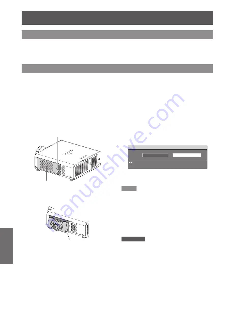
Procedure of ACF unit replacement

Loosen “ACF cover fixing screw” (1 

1 ) 

screw) until the screws turn freely and 

remove the “ACF cover”.

Slide out the “ACF unit” from the 

2 ) 

projector slowly.

When you replace the “ACF unit”, clean the 


z

compartment and/or the air exhaust port if you 

need to.

Insert the new “ACF unit” into the 

3 ) 

compartment in correct direction and 

slightly push until it clicks.

Attach the “ACF cover” and tighten 

4 ) 

“ACF cover fixing screw” (1 screw) 

securely.
Select [FILTER COUNTER RESET] 

5 ) 

in [PROJECTOR SETUP] menu, and 

press <ENTER> button.  (

Æ

page 86)

Press ◄► to select [OK], and press 

6 ) 

<ENTER> button.

Note

When the ACF unit is not installed, the filter indicator will 


z

blink in red and the power will turn off in 10 minutes. (The 

time before the power is turned off is indicated by the unit 

of 1 minute.)

The replacement timing of the ACF depends on 


z

environment of usage.

When resetting is performed, the filter will be wound.


z

The part numbers of accessories and separately sold 


z

components are subject to change without notice.

Always install the ACF unit when using the projector.


z

Attention

When installing the ACF unit, take care not to touch the 


z

filter surface.

Be sure to install the ACF unit when using the projector.


z

The ACF unit to be replaced should be an unused 


z

product.

ACF cover

ACF cover fixing screw

ACF unit

CANCEL

OK

EXECUTE

CHANGE

[ENTER]

RESET FILTER COUNTER?

Summary of Contents for PT-DS100XE ( )

Page 1: ...r Before operating this product please read the instructions carefully and save this manual J J for future use Before using your projector be sure to read J J Precautions with regard to safety Æ pages 9 to 17 TQBJ0342 2 Model No PT DZ110XE PT DS100XE PT DW90XE ENGLISH The projection lens is sold separately M0710KY3031 DW ...

Page 2: ...f time 2 To prevent electric shock do not remove cover No user serviceable parts inside Refer servicing to qualified service personnel 3 Do not remove the earthing pin on the mains plug This apparatus is equipped with a three prong earthingtype mains plug This plug will only fit an earthing type mains socket This is a safety feature If you are unable to insert the plug into the mains socket contac...

Page 3: ...mation about collection and recycling of old products and batteries please contact your local municipality your waste disposal service or the point of sale where you purchased the items Penalties may be applicable for incorrect disposal of this waste in accordance with national legislation For business users in the European Union If you wish to discard electrical and electronic equipment please co...

Page 4: ...of safely There is a danger of severe electrical shock if the cut off plug is inserted into any 13 amp socket If a new plug is to be fitted please observe the wiring code as shown below If in any doubt please consult a qualified electrician WARNING THIS APPLIANCE MUST BE EARTHED IMPORTANT The wires in this power cord are colored in accordance with the following code Green and Yellow Blue Brown Ear...

Page 5: ...E When four lamps are used Approx 3 000 hours PT DZ110XE two lamps LAMP POWER HIGH The standby power is much less than the existing model Approx 25 W PT D10000E Approx 0 3 W PT DZ110XE STANDBY MODE ECO Reduced in size Lengthened lamp replacement cycle Reduced standby power Quick steps J J For details see the corresponding pages 1 Set up your projector Æpage 22 2 Attach the projection lens Æpage 38...

Page 6: ...ptional 38 How to install the projection lens 38 How to remove the projection lens 38 Basic Operation Powering ON OFF 39 Connecting the power cord 39 Powering up the projector 40 Making adjustment and selection 40 Powering off the projector 41 Direct power off function 41 Projecting 42 Selecting the input signal 42 How to adjust the focus zoom and shift 42 Adjustment range after lens position opti...

Page 7: ...74 ON SCREEN DISPLAY 74 BACK COLOR 75 STARTUP LOGO 75 FREEZE 75 PROJECTOR SETUP menu 76 PROJECTOR ID 76 INSTALLATION 76 HIGH ALTITUDE MODE 76 COOLING CONDITION 77 LAMP SELECT 77 LAMP RELAY 77 LAMP POWER 78 BRIGHTNESS CONTROL 78 STANDBY MODE 82 SCHEDULE 82 RS 232C 83 STATUS 84 NO SIGNAL SHUT OFF 85 REMOTE2 MODE 85 FUNCTION BUTTON 85 DATE AND TIME 85 LENS CALIBRATION 86 FILTER COUNTER RESET 86 SAVE ...

Page 8: ...acement 110 Before replacing the unit 110 Replacing the unit 110 Troubleshooting 113 Appendix Technical Information 115 PJLink protocol 115 Control commands via LAN 116 Serial terminal 118 REMOTE 2 IN terminal 121 Two window display combination list 122 Restoring the MENU LOCK PASSWORD to default 122 List of compatible signals 123 Specifications 125 Dimensions 127 About brand 127 Ceiling mount bra...

Page 9: ...which are damaged or wall outlets which are coming loose from the wall z z Clean the power plug regularly to prevent it from becoming covered in dust Failure to observe this will cause a fire If dust builds up on the power plug the resulting humidity can damage the insulation z z If not using the projector for an extended period of time pull the power plug out from the wall outlet z z Pull the pow...

Page 10: ...e your hands directly into this light z z Be especially careful not to let young children look into the lens In addition turn off the power and disconnect z z the power plug when you are away from the projector Do not insert any foreign objects into the projector Doing so will cause fire or electric shocks Do not insert any metal objects or flammable objects into the projector or drop them onto th...

Page 11: ...injury Lamp replacement The lamp has high internal pressure If improperly handled an explosion and severe injury or accidents will result Replacement of the lamp should be carried out by a qualified technician z z The lamp can easily explode if struck against hard objects or dropped z z Before replacing the lamp be sure to disconnect the power plug from the wall outlet z z Electric shocks or explo...

Page 12: ...an damage the cables which will cause fire or electric shocks to occur Do not place your hands in the openings beside the optical lens while shifting the lens Failure to observe this could cause injury ACCESSORIES Do not use the old lamp unit If used it could cause lamp explosion If the lamp has broken ventilate the room immediately Do not touch or bring your face close to the broken pieces Failur...

Page 13: ...l power lines or power sources Do not install the projector at elevations higher than 2 700 m 8 858 ft above sea level z z If using this projector at high elevations 1 400 2 700 m 4 593 8 858 ft above sea level set HIGH ALTITUDE MODE to ON If using this projector at elevations lower than 1 400 m 4 593 ft above sea level set HIGH ALTITUDE MODE to OFF Failure to observe this will result in malfuncti...

Page 14: ...installation However do not use the screw z z holes for them to fix the projector Do not tighten other screws etc into the screw holes for the adjustable feet Doing so can break the set When installing the removed adjustable feet again note that the front and rear ones have different lengths The longer screws are used for front feet Length of front leg screw 65 mm Length of rear leg screw 23 mm Wh...

Page 15: ...product z z Unauthorized operation of this product by a malicious third party z z Interfering or stopping of this product by a malicious third party z z Security instruction The connecting network must be secured by firewall or others z z Change your password regularly z z Do not use a password that is simple to guess z z Panasonic and its affiliate companies would never directly inquire about you...

Page 16: ...y available shielded interface cable Optical components It may be necessary to replace the optical components such as DLP chips and Polarizing plates in less than 1 year if using the projector in a high temperature environment or in a very dusty oily smoke or tobacco smoke environment For more details please contact your dealer DLP chips The DLP chips are precision made Note that in rare cases pix...

Page 17: ...cables x2 Washers x4 Wire rope fixing screw x2 CD ROM x1 TXFQB02VKN AA R6 batteries for remote control x2 Lens fixing screw x1 XYN4 J18FJ Attention After unpacking the projector discard the power cord cap and packaging material properly z z For lost accessories consult your dealer z z The part numbers of accessories and separately sold components are subject to change without notice z z Store smal...

Page 18: ...Bottom view J J Remote control wired terminal Æpage 21 Remote control signal emitters Specifies the ID of the remote control Æpage 21 Restores the default factory setting Æpage 50 Assign the frequently use functions from options for shortcut Æpage 48 These buttons are used together with to adjust focus zoom and shift by the projection lens Æpages 40 42 Switches the image aspect ratio Æpage 49 Pres...

Page 19: ...justers Screw up down to adjust the projection angle Lamp2 indicator LAMP2 Indicates the lamp2 unit status Æpage 108 Lamp1 indicator LAMP1 Indicates the lamp1 unit status Æpage 108 Power indicator STANDBY R ON G Indicates the power supply status Security lock Air intake port Terminals on side CONTROL PANEL AC IN terminal Connect the power cord to supply electronic power to the projector MAIN POWER...

Page 20: ...internal mechanical shutter to black out the projector Æpage 47 ENTER button Press to activate a menu selection or to initiate a function LENS button This button is used together with to adjust focus zoom and shift by the projection lens MENU button Displays and clears the main menu and returns to the previous menu when the menu is displayed If you hold it down for at least 3 seconds while the on ...

Page 21: ...stored in the remote control z z unit unless another one is specified later However the stored ID will be erased if the batteries of the remote control are left exhausted When the batteries are replaced set the same ID number again The ID number can be set to ALL or from 1 to 64 z z Note Refer to PROJECTOR ID of PROJECTOR SETUP z z menu Æpage 76 Using a wired remote control When multiple projector...

Page 22: ... Menu Û Method INSTALLATION FRONT CEILING COOLING CONDITION CEILING SETTING Menu Û Method INSTALLATION REAR FLOOR COOLING CONDITION FLOOR SETTING Mounting on the ceiling and J J projecting from rear Using translucent screen Setting on a desk floor and J J projecting from front Menu Û Method INSTALLATION REAR CEILING COOLING CONDITION CEILING SETTING Menu Û Method INSTALLATION FRONT FLOOR COOLING C...

Page 23: ...rea m SW Width of the projection area m H Vertical distance between the lens center level and the bottom edge of the projected image m SD Diagonal length of the projection area m LW Minimum distance LT Maximum distance Attention Before installing please read z z Precautions with regard to safety Æ pages 9 to 17 Special care should be used when DLP projectors are used in the same room as high power...

Page 24: ...0 15 5 5 1 2 2 4 0 6 1 2 ET D75LE3 40 15 10 10 0 8 1 6 0 4 0 8 ET D75LE4 40 15 10 15 0 6 1 0 0 3 0 5 ET D75LE5 22 15 5 5 3 0 6 0 1 5 3 0 4 3 ET D75LE6 28 10 5 5 2 4 4 8 1 2 2 4 2 6 ET D75LE8 40 15 10 15 0 4 0 8 0 2 0 4 ET D75LE10 40 15 5 5 1 6 3 2 0 8 1 6 ET D75LE20 40 15 5 5 1 6 3 2 0 8 1 6 ET D75LE30 40 15 5 5 1 2 2 4 0 6 1 2 Note When using geometric adjustment if the amount of compensation is ...

Page 25: ...79 37 149 08 15 24 600 8 077 12 923 17 83 23 82 23 94 35 93 35 94 60 06 60 07 95 60 95 32 178 96 Lens type Zoom lens Fixed focus lens Model number of projection lens ET D75LE6 ET D75LE10 ET D75LE20 ET D75LE30 ET D75LE5 Throw ratio Û 0 9 1 1 1 1 3 1 7 1 1 7 2 4 1 2 4 4 7 1 0 7 1 Screen dimensions Projection distance L Screen size Effective height SH Effective width SW Min LW Max LT Min LW Max LT Mi...

Page 26: ... 13 283 18 33 24 49 24 61 36 93 36 94 61 73 61 74 98 26 97 98 183 95 Lens type Zoom lens Fixed focus lens Model number of projection lens ET D75LE6 ET D75LE10 ET D75LE20 ET D75LE30 ET D75LE5 Throw ratio Û 0 9 1 1 1 1 3 1 7 1 1 7 2 4 1 2 4 4 7 1 0 7 1 Screen dimensions Projection distance L Screen size Effective height SH Effective width SW Min LW Max LT Min LW Max LT Min LW Max LT Min LW Max LT Fi...

Page 27: ...12 192 20 20 26 98 27 12 40 69 40 70 68 01 68 02 108 24 107 96 202 65 Lens type Zoom lens Fixed focus lens Model number of projection lens ET D75LE6 ET D75LE10 ET D75LE20 ET D75LE30 ET D75LE5 Throw ratio Û 1 1 1 3 1 1 6 2 0 1 2 0 2 9 1 2 9 5 6 1 0 8 1 Screen dimensions Projection distance L Screen size Effective height SH Effective width SW Min LW Max LT Min LW Max LT Min LW Max LT Min LW Max LT F...

Page 28: ...81 59 153 23 15 24 600 9 144 12 192 18 33 24 49 24 61 36 93 36 94 61 73 61 74 98 26 97 98 183 95 Lens type Zoom lens Fixed focus lens Model number of projection lens ET D75LE6 ET D75LE10 ET D75LE20 ET D75LE30 ET D75LE5 Throw ratio Û 1 0 1 2 1 1 4 1 8 1 1 8 2 6 1 2 6 5 1 1 0 8 1 Screen dimensions Projection distance L Screen size Effective height SH Effective width SW Min LW Max LT Min LW Max LT Mi...

Page 29: ... 283 19 97 26 69 26 82 40 24 40 25 67 26 67 26 107 04 106 77 200 41 Lens type Zoom lens Fixed focus lens Model number of projection lens ET D75LE6 ET D75LE10 ET D75LE20 ET D75LE30 ET D75LE5 Throw ratio Û 1 0 1 2 1 1 4 1 8 1 1 8 2 6 1 2 6 5 1 1 0 8 1 Screen dimensions Projection distance L Screen size Effective height SH Effective width SW Min LW Max LT Min LW Max LT Min LW Max LT Min LW Max LT Fix...

Page 30: ...91 16 171 16 15 24 600 7 472 13 283 20 48 27 36 27 49 41 25 41 26 68 95 68 96 109 74 109 47 205 46 Lens type Zoom lens Fixed focus lens Model number of projection lens ET D75LE6 ET D75LE10 ET D75LE20 ET D75LE30 ET D75LE5 Throw ratio Û 1 0 1 2 1 1 4 1 9 1 1 8 2 7 1 2 7 5 2 1 0 8 1 Screen dimensions Projection distance L Screen size Effective height SH Effective width SW Min LW Max LT Min LW Max LT ...

Page 31: ...4 12 192 25 09 33 52 33 68 50 53 50 54 84 45 84 45 134 38 134 11 251 62 Lens type Zoom lens Fixed focus lens Model number of projection lens ET D75LE6 ET D75LE10 ET D75LE20 ET D75LE30 ET D75LE5 Throw ratio Û 1 4 1 6 1 1 9 2 5 1 2 5 3 6 1 3 6 6 9 1 1 0 1 Screen dimensions Projection distance L Screen size Effective height SH Effective width SW Min LW Max LT Min LW Max LT Min LW Max LT Min LW Max LT...

Page 32: ...1013 4 6 7 4 1 16 9 Min L 4 0591 SD m 0 1158 Max L 6 4528 SD m 0 1013 5 6 8 9 1 4 3 Min L 4 4724 SD m 0 1158 Max L 7 1102 SD m 0 1013 ET D75LE8 7 3 13 8 1 16 10 Min L 6 2795 SD m 0 3862 Max L 11 7677 SD m 0 3598 7 3 13 8 1 16 9 Min L 6 4567 SD m 0 3862 Max L 12 0945 SD m 0 3598 8 8 16 5 1 4 3 Min L 7 1102 SD m 0 3862 Max L 13 3189 SD m 0 3598 ET D75LE6 0 9 1 1 1 16 10 Min L 0 7913 SD m 0 0566 Max ...

Page 33: ...591 SD m 0 1158 Max L 6 4528 SD m 0 1013 16 9 Min L 4 4213 SD m 0 1158 Max L 7 0315 SD m 0 1013 ET D75LE8 7 9 15 0 1 4 3 Min L 6 4567 SD m 0 3862 Max L 12 0945 SD m 0 3598 8 0 15 0 1 16 9 Min L 7 0315 SD m 0 3862 Max L 13 1732 SD m 0 3598 ET D75LE6 1 0 1 2 1 4 3 Min L 0 8150 SD m 0 0566 Max L 0 9764 SD m 0 0736 16 9 Min L 0 8858 SD m 0 0566 Max L 1 0630 SD m 0 0736 ET D75LE10 1 4 1 8 1 4 3 Min L 1...

Page 34: ... 0 3598 10 9 20 6 1 4 3 Min L 8 8228 SD m 0 3862 Max L 16 5354 SD m 0 3598 ET D75LE6 1 0 1 2 1 16 9 Min L 0 9094 SD m 0 0566 Max L 1 0906 SD m 0 0736 1 4 1 6 1 4 3 Min L 1 1142 SD m 0 0566 Max L 1 3346 SD m 0 0736 ET D75LE10 1 4 1 9 1 16 9 Min L 1 2756 SD m 0 0857 Max L 1 6496 SD m 0 1085 1 9 2 5 1 4 3 Min L 1 5630 SD m 0 0857 Max L 2 0197 SD m 0 1085 ET D75LE20 1 8 2 7 1 16 9 Min L 1 6339 SD m 0 ...

Page 35: ...atible with the projector z z When using long cables to connect with each of equipment to the projector there is a possibility that the image z z will not be output correctly unless a compensator is used Pin assignments and signal names of S VIDEO IN terminal J J Outside view Pin No Signal names GND luminance signal GND color signal Luminance signal Color signal Pin assignments and signal names of...

Page 36: ... If this is the case connect a TBC between the z z projector and the video deck Note When using an HDMI cable check that it is compliant with the HDMI standard Using a cable that is not compliant with the z z HDMI standard may result in problems such as the image cutting out or not appearing When connecting the 1 080p signal using HDMI use a cable compliant with 1 080p signal It is possible to con...

Page 37: ... terminals z z When using the DVI D input EDID settings may be required for the connected device z z Æpage 73 When using an HDMI cable check that it is compliant with the HDMI standard Using a cable that is not compliant with the z z HDMI standard may result in problems such as the image cutting out or not appearing When connecting the 1 080p signal using HDMI use a cable compliant with 1 080p sig...

Page 38: ...head screwdriver There is not the projection lens fixing tap hole on all the lenses How to remove the projection lens Remove the Lens fixing screw 1111 Remove the first screw on the right side of the z z mark orange of the projection lens with a Phillips head screwdriver While holding down the LOCK 2222 button turn the projection lens counterclockwise and then pull it off Turn the projection lens ...

Page 39: ...cord securely to its base to prevent it from coming off Before connecting the power cord confirm that the MAIN POWER switch is in the OFF position Installation J J Insert the plug securely until its right and left claw click Removal J J Remove the power cord from the electrical outlet while pressing the knobs on its sides ...

Page 40: ...ure around the projector so that it is 0 C or higher and then turn on the MAIN POWER switch and the POWER ON switch once more With ECO setting in Standby mode z z Æpage 82 When switch on the projector projection will start about 10 seconds late If the filter is not installed the power is turned off z z automatically after 10 minutes If projection was stopped last time by using the DIRECT z z POWER...

Page 41: ... power supply again when the lamp has been cooled sufficiently Failure to observe this may shorten the lamp life The projector consumes approximately 8 W 240 V z z mode power STANDBY MODE NORMAL Direct power off function The power supplied internally causes the cooling fan to continue operating and cool off in the event that the power has failed or even after the power cord is accidentally disconn...

Page 42: ...e remote control J J Press LENS FOCUS ZOOM SHIFT 1111 button on the remote control Press FOCUS button z z Adjust focus Press ZOOM button z z Adjust zoom Press SHIFT button z z Adjust focus Press to select an item and 2222 adjust it Note Be careful not to catch your fingers between the lens and z z shroud when shifting the lens The zoom adjustment menu will be displayed only when z z a lens with zo...

Page 43: ...ift adjustment cannot be carried out z z 0 44 V 0 12 V 0 15 H Standard projection position 0 44 V 0 12 V 0 15 H 0 12 V Projected screen height V 0 12 V Projected screen width H 0 55 V 0 12 V 0 2 H Standard projection position 0 55 V 0 12 V 0 2 H 0 12 V Projected screen height V 0 12 V Projected screen width H 0 40 V 0 12 V 0 2 H Standard projection position 0 40 V 0 12 V 0 2 H 0 12 V Projected scr...

Page 44: ...tion z z Attention HOME POSITION for the projection lens is the lens position when the lens is being replaced or when the projector is z z being stored away and it is not the optical center of the screen Lens adjustment to compensate for uneven screen focus About the focus balance J J Relationship between lens orientation and screen focus Q Q If the projection lens is tilted with respect to the pl...

Page 45: ...lens mount may be used to compensate for uneven screen focus Structure of lens mount Q Q The three adjustment screws allow the lens to be tilted up and down and three more screws lock down the adjustment Figure 2 Front view of lens mount when viewed from screen side Lens bracket Locking screw Adjust the focus adjustment screws and after installing the lens ...

Page 46: ...oosened in step 3 counterclockwise slightly till the out of focus image sides are in focus Turning the screws counterclockwise moves the lens bracket and tilts the lens toward the screen Readjust the lens shift position with the remote if needed Refocus the image as in steps 1 and 2 above Fine adjust the focus evenness as needed as described in step 4 When adjustment is complete tighten the lockin...

Page 47: ...button on the remote control Switching the input signal You can use the remote control to switch the signals that are being input and projected button Press INPUT SELECT button on the remote control or the main unit RGB1 Switches to RGB1 input RGB2 Switches to RGB2 input DVI D HDMI Switches to DVI D or HDMI input If either of the inputs has already been selected the input switches to the other VID...

Page 48: ...age 72 AUTO SETUP may not be available depending on the z z machine type of the personal computer Automatic adjustment may not available for z z synchronization signal of C SYNC and G SYNC Image may be distorted for several seconds during z z automatic adjustment This is not a malfunction For every supplied signal adjustment is required z z Automatic adjustment can be canceled by pressing z z MENU...

Page 49: ...CT button on the remote control The setting will change as follows each time z z ASPECT button is pressed VID AUTO 1 DEFAULT S1 AUTO 3 VID AUTO PRI 3 AUTO 2 THROUGH HV FIT 16 9 V FIT H FIT 4 3 VIDEO S VIDEO NTSC only RGB1 RGB2 480i 480p only S VIDEO NTSC only Note Some aspect ratios may not be available for selection z z depending on the input signal Refer to ASPECT of POSITION menu Æpage 59 for d...

Page 50: ...tment screen is displayed the screen will return to the previous page J J Resetting to the factory default If an adjustment item is selected and DEFAULT button is pressed the adjustment value will return to the factory default setting Press 0 Note You cannot reset all the settings at a time to the factory z z default settings To reset all the settings to the factory defaults refer to INITIALIZE of...

Page 51: ... menu item Default Page PICTURE MODE STANDARD 53 CONTRAST 0 54 BRIGHTNESS 0 54 COLOR 0 54 TINT 0 54 COLOR TEMPERATURE DEFAULT 55 GAMMA DEFAULT 56 SYSTEM DAYLIGHT VIEW OFF 56 SHARPNESS 6 57 NOISE REDUCTION 2 57 DYNAMIC IRIS 2 57 SYSTEM SELECTOR YPBPR 1 58 Note The factory default values may vary depending on the z z PICTURE MODE POSITION J J Sub menu item Default Page SHIFT 59 ASPECT DEFAULT 1 59 Z...

Page 52: ...C 83 STATUS 84 NO SIGNAL SHUT OFF DISABLE 85 REMOTE2 MODE DEFAULT 85 FUNCTION BUTTON 85 DATE AND TIME 85 LENS CALIBRATION 86 FILTER COUNTER RESET 86 SAVE ALL USER DATA 87 LOAD ALL USER DATA 87 INITIALIZE 87 SERVICE PASSWORD 87 P IN P J J Details Æpage 88 TEST PATTERN J J Details Æpage 89 SIGNAL LIST J J Details Æpage 90 SECURITY J J Sub menu item Default Page SECURITY PASSWORD OFF 92 SECURITY PASS...

Page 53: ...RGB system and z z STANDARD for moving images DICOM is an abbreviation for Digital Imaging and z z Communication in Medicine which is a standard for medical imaging devices Although the name DICOM is used this projector is not a medical device Accordingly do not use the projected images for medical diagnosis or similar usage When ENTER button is pressed while a PICTURE z z MODE other than USER is ...

Page 54: ...the level 3333 Operation Adjustment Adjustment range Press Increases the brightness of the dark black parts of the screen Maximum value 31 Press Reduces the brightness of the dark black parts of the screen Minimum value 31 COLOR You can adjust the color saturation of the projected image Press to select COLOR 1111 Press or ENTER button 2222 The COLOR individual adjustment screen will z z be display...

Page 55: ...HIGH or WHITE BALANCE LOW Press ENTER button 9999 The WHITE BALANCE HIGH or LOW z z screen will be displayed Press to select RED GREEN 11111 or BLUE Press to adjust the level 11111 Item Operation Adjustment Adjustment range RED Press Deepens red Maximum value HIGH 255 LOW 127 Minimum value HIGH 0 LOW 127 Default HIGH 255 LOW 0 Press Weakens red GREEN Press Deepens green Press Weakens green BLUE Pr...

Page 56: ... projector is not a medical device Do not use the displayed image for diagnosis Changing the name of USER1 J J or USER2 Select USER1 or USER2 in step 3 111 Press ENTER button 222 The GAMMA screen will be displayed z z Press to select GAMMA NAME 333 CHANGE Press ENTER button 444 The GAMMA NAME CHANGE screen will be z z displayed Press to select characters 5555 and press ENTER button to input them P...

Page 57: ...so set to OFF DYNAMIC IRIS Pictures with the optimum contrast will be displayed by automatically providing aperture compensation and signal compensation to suit the pictures concerned Press to select DYNAMIC IRIS 1111 Press or ENTER button 2222 The DYNAMIC IRIS individual adjustment z z screen will be displayed Press to switch DYNAMIC IRIS 3333 The setting will change as follows each time z z is p...

Page 58: ... problems could be z z encountered with some equipment HDMI terminal input signal J J 480p 576p signals z z Select from Auto RGB and YCBCR Other signals z z Select from Auto RGB and YPBPR Note Refer to z z List of compatible signals Æpage 123 for available signals Malfunction may occur or other problems could be z z encountered with some equipment SDI terminal input signal J J PT DZ110XE PT DS100X...

Page 59: ...REEN SETTING Set SCREEN SETTING first Æpage 70 Press to select ASPECT 1111 Press or ENTER button 2222 The ASPECT individual adjustment screen will z z be displayed Press to switch ASPECT 3333 The setting will change as follows each time z z is pressed VID AUTO 1 DEFAULT S1 AUTO 3 VID AUTO PRI 3 AUTO 2 THROUGH HV FIT 16 9 V FIT H FIT 4 3 VIDEO S VIDEO NTSC only RGB1 RGB2 480i 480p only S VIDEO NTSC...

Page 60: ...the screen aspect set with SCREEN FORMAT is performed and then the pictures are displayed Standard signals are input signals with an aspect ratio of 4 3 or 5 4 Wide screen signals are input signals with an aspect ratio of 16 10 16 9 15 9 or 15 10 Note Some size modes are not available for certain types of z z input signals For NTSC signals DEFAULT cannot be selected If an aspect ratio which is dif...

Page 61: ...put is applied is unstable No optimal value may be obtained if the total number of z z dots is not correct The CLOCK PHASE can be adjusted only when RGB z z signal input is applied with RGB1 and RGB2 IN GEOMETRY PT DZ110XE PT DS100XE only Square video can be projected onto a special shaped screen using unique image processing technology Press to select GEOMETRY 1111 Press to switch GEOMETRY 2222 T...

Page 62: ... used the projection distance divided by the screen width VERTICAL KEYSTONE z z HORIZONTAL KEYSTONE z z VERTICAL ARC z z HORIZONTAL ARC z z VERTICAL BALANCE z z HORIZONTAL BALANCE z z Note When GEOMETRY setting is set displayed menu or z z startup logo might be projected outside of the actual image area If both EDGE BLENDING z z Æpage 65 adjustment and GEOMETRY correction are used EDGE BLENDING ad...

Page 63: ...t 4444 KEYSTONE J J SUB KEYSTONE J J LINEARITY J J Note When KEYSTONE setting is set displayed menu or z z startup logo might be projected outside of the actual image area You can correct the distortion 40 from the plane For z z a better quality image installing the projector with a minimum of distortion is recommended ET D75LE5 22 ET D75LE6 28 Some distortion may be retained for lens shift adjust...

Page 64: ...ED is selected when the signal is not a 2 2 pulldown signal BLANKING Blanking adjustment fine tunes the images projected by the video deck or other devices when the noise appears on the edges of the screen or if a part of the image lies slightly offscreen Press to select BLANKING 1111 Press ENTER button 2222 The BLANKING screen will be displayed z z Press to select the desired item 3333 for adjust...

Page 65: ...from 1 to 255 z z The optimal value for the clamp position z z adjustment If dark areas are crushed The optimal value is the point where the dark area is best improved If the dark areas are displayed in green The optimal value is the point where the green areas become black and the crushing effect is rectified Note The CLAMP POSITION can be adjusted only when the z z RGB signal input is applied wi...

Page 66: ...IGHT INSIDE setting 0 to 255 Press to select BRIGHT 1111 OUTSIDE Press ENTER button 1111 The BRIGHT OUTSIDE individual adjustment z z screen will be displayed When INTERLOCKED is set to OFF z z individual adjustment of RED GREEN and BLUE will be possible Press to select an item and 1111 press to adjust the setting Note The BRIGHT INSIDE adjustments are used to match z z the projector s main screen...

Page 67: ...his is the standard setting SHORT Shortens the delay at the expense of some picture quality Note When FRAME DELAY is set to SHORT deterioration z z in the picture quality will occur Furthermore the noise reduction function cannot be used RASTER POSITION When the scaler is set such that the image is smaller than the display area the image can be moved to any position inside the display area Press t...

Page 68: ...e on screen display language Menus setting items adjustment screens and z z control button names will be displayed in the language the user chooses The available languages are English German z z DEUTSCH French FRANÇAIS Spanish ESPAÑOL Italian ITALIANO Japanese Chinese Russian русский and Korean Note The on screen display of the projector is set to the z z English language on shipping DISPLAY LANGU...

Page 69: ...ED 7COLORS GREEN 7COLORS BLUE 7COLORS CYAN 7COLORS MAGENTA 7COLORS YELLOW or 7COLORS WHITE screen will be displayed If AUTO TEST PATTERN is turned ON the z z test pattern of the selected color is displayed Press to adjust the values 6666 These values can be adjusted from 0 off to z z 2 048 full gain Note The effects of correcting the adjustment color z z When tuning the correction color that is th...

Page 70: ...a has been input 11111 press MENU button Note If 709MODE has been selected as the COLOR z z MATCHING setting the 3 primary colors defined by the ITU R BT 709 standard will be set as the target data If the target data is outside the color range of the z z projector the colors will not be projected correctly LARGE SCREEN CORRECTION When viewing images close up on a large screen you can correct the c...

Page 71: ...RED Line selection BLUE Line selection GREEN Note Setting can also be performed using the FUNCTION z z button Æpage 85 Adjust the waveform J J Project the brightness adjustment signal from for example a commercially available adjustment disc 0 0 IRE or 7 5 IRE 100 100 IRE and adjust the waveform Adjusting brightness Q Q Select Line selection BRIGHTNRSS 1111 in the waveform monitor Adjust the black...

Page 72: ...hen AUTO SETUP button is pressed the projected image position will be adjusted ON If unregistered signals are input when ON is selected auto setup will be initiated automatically AUTO SETUP Use this setting when adjusting a specific or oblong 16 9 etc signal Press to select AUTO SETUP 1111 Press ENTER button 2222 The AUTO SETUP screen will be displayed z z Press to select MODE 3333 Press to switch...

Page 73: ...of the synchronous signal input Press to select RGB IN 1111 Press ENTER button 2222 The z z RGB IN screen will be displayed Press to select RGB1 SYNC 3333 TERMINAL or RGB2 SYNC TERMINAL Press to switch 4444 The setting will change as follows each time z z is pressed LOW HIGH LOW Input impedance is set to LOW HIGH Input impedance is set to HIGH DVI D IN Change this setting if video does not display...

Page 74: ...d to HDMI IN using a conversion cable etc 64 940 Select this when for example an HDMI terminal output of an external device DVD player etc is connected to HDMI IN Note The optimal setting differs depending on the output z z setting of the connected external device Refer to the instruction manual for the external device The displayed HDMI signal level is the value when the z z input is 30 bit SDI I...

Page 75: ...will appear black LOGO1 The picture registered by the user will be projected in the projection area LOGO2 The Panasonic logo is projected Note Separate software is required in order to create the z z pictures to use for LOGO1 Consult your dealer STARTUP LOGO This sets the startup logo that is projected when the power is turned on Press to select STARTUP LOGO 1111 Press to switch STARTUP LOGO 2222 ...

Page 76: ...de down or in reverse change the projection scheme Select the setting by displaying the on screen z z indications using buttons of the remote control or the control panel on the main unit Press to select INSTALLATION 1111 Press to switch INSTALLATION 2222 The setting will change as follows each time z z is pressed FRONT FLOOR FRONT CEILING REAR CEILING REAR FLOOR FRONT FLOOR Setting on a desk floo...

Page 77: ...tive lamp exceeds 3 000 hours of cumulative operating time when HIGH is selected as the LAMP POWER setting the other lamp alone will light However if both lamps remain off or the 3 000 hours of cumulative operating time when HIGH is selected as the LAMP POWER setting are exceeded the projector will enter the standby mode The colors of the items indicate the status z z Green Current setting Yellow ...

Page 78: ...hen multiple screens are projected using multiple projectors Press to select BRIGHTNESS 1111 CONTROL GAIN Press to adjust 2222 Operation Adjustment Adjustment range Brightness Max quantity of brightness control Press Increases Decreases Maximum value 100 Press Decreases Increases Minimum value 20 Note When using one projector the maximum quantity of z z brightness control is obtained by subtractin...

Page 79: ... While MODE of the brightness control is set to AUTO z z or PC the DYNAMIC IRIS function is kept OFF No correction While MODE of the brightness control is set to AUTO z z or PC the LAMP POWER is fixed to HIGH or LOW When changing the lamp power return MODE of the brightness control to OFF then change the lamp power and adjust the brightness control again While MODE of the brightness control is set...

Page 80: ...yed The group to be linked is displayed The name and IP address of this projector are displayed The projector name and IP address of the same group detected through the network are displayed The state is indicated by color GREEN The brightness can be corrected by a significant margin YELLOW The brightness can no longer be corrected by a significant margin RED There is an error in brightness contro...

Page 81: ...e sub nets of the projectors are the same The LINKS are set in the same group For changing the projector name refer to z z NETWORK SETUP of NETWORK menu Æpage 95 or Network config page Æpage 107 When MODE of brightness control is Q Q set to PC The name of this projector is displayed The state is indicated by color GREEN The brightness can be corrected by a significant margin YELLOW The brightness ...

Page 82: ...utput z z and some of RS 232C commands are not available When switch on the projector projection will start about 10 seconds late SCHEDULE This sets the command execution schedule for each day of the week How to enable the SCHEDULE J J function Press to select SCHEDULE 1111 Press to switch SCHEDULE 2222 The setting will change as follows each time z z is pressed ON OFF Note If SCHEDULE is set to O...

Page 83: ... 3333 conditions press to change the setting 4444 Note Refer to Serial terminal z z Æpage 118 Selecting items in EMULATE J J When using the control commands for one of our projectors that you have previously purchased to control this projector using a computer via its serial input terminal set up the EMULATE function as follows This will allow you to use the control software etc designed for our e...

Page 84: ...filter remaining quantity PROJECTOR TYPE Displays type of projector SERIAL NUMBER Displays the serial number of the projector LAMP UNIT MODEL NO Displays the component number of the lamp unit LAMP1 SERIAL NUMBER Displays the serial number for lamp1 LAMP2 SERIAL NUMBER Displays the serial number for lamp2 MAIN VERSION Displays the main version of the firmware of the projector unit SUB VERSION Displ...

Page 85: ...0 compatible REMOTE 2 terminal FUNCTION BUTTON You can assign a certain menu function to the FUNCTION button as shortcut Press to select FUNCTION 1111 BUTTON Press ENTER button 2222 The FUNCTION BUTTON screen will be z z displayed Press to select a function 3333 DISABLE Deactivate the FUNCTION button P IN P Changes between OFF USER1 USER2 USER3 in P IN P Æpage 88 SUB MEMORY Displays the assigned S...

Page 86: ...s automatically sets the limit value of the lens shift and the home position of the projector Press to select LENS 1111 CALIBRATION Press ENTER button 2222 A confirmation message will be displayed z z Press to select OK and press 3333 ENTER button To stop select CANCEL z z The lens will move vertically and horizontally z z and the limit value of the lens shift and home position are set automatical...

Page 87: ...s INITIALIZE This returns various setting values to their factory default settings Press to select INITIALIZE 1111 Press ENTER button 2222 The SECURITY PASSWORD screen will be z z displayed Enter the password set for the 3333 SECURITY PASSWORD The INITIALIZE screen will be displayed z z Press to select the desired 4444 initialize item ALL USER DATA All setting values including ENTRY SIGNAL NETWORK...

Page 88: ...The user can specify the display position of the main window on the screen SUB WINDOW The input terminal for the subwindow is displayed Press to select an item and press ENTER button to switch to the item SIZE The user can specify the display size of the sub window between 10 and 100 POSITION The user can specify the display position of the subwindow on the screen CLOCK PHASE Set this if the pictu...

Page 89: ...input signal is displayed before performing various kinds of setting Press to select the required test 1111 pattern Cycle of displayed internal test J J patterns The setting will change as follows each time is pressed MENU screen Focus MENU screen Entry screen MENU screen Color bars HORIZONTAL MENU screen All white MENU screen Color bars VERTICAL MENU screen All black MENU screen Window inversion ...

Page 90: ... be z z registered at the instant they are input Renaming a registered data Press to select the required 1111 signal data Press ENTER button 2222 The REGISTERED SIGNAL STATUS screen z z will be displayed Displays the character list z z Press MENU button to return to the z z REGISTERED SIGNAL LIST screen Press ENTER button 3333 The RENAME screen will be displayed z z Press to select characters 4444...

Page 91: ...naming a registered data follow the same z z procedure steps 4 5 of Renaming a registered data Æpage 90 J J Displaying the sub memory list and restoring the settings In the normal screen when the menu 1111 is not displayed press button The SUB MEMORY LIST screen will be z z displayed Press to select the required 2222 sub memory data and press ENTER button The REGISTERED SIGNAL STATUS screen z z wi...

Page 92: ...z z is pressed OFF ON OFF Deactive ON Active Note PASSWORD is set to OFF by default and when z z initialized Change the SECURITY PASSWORD regularly and make z z it uneasy to guess The security password becomes valid when setting of z z the security password is turned ON and then the MAIN POWER switch is turned off SECURITY PASSWORD CHANGE The password can be changed Press to select SECURITY 1111 P...

Page 93: ...d z z MENU LOCK You can lock MENU button function and the password will be asked to display the menu every time Press to select MENU LOCK 1111 Press to switch MENU LOCK 2222 The setting will change as follows each time z z is pressed OFF ON OFF Deactivate the MENU LOCK system ON Activate the MENU LOCK system Note Once MENU LOCK is set to ON you cannot use z z MENU button unless you input the corre...

Page 94: ...ABLE Enables control from the remote control DISABLE Disables control from the remote control Press to select ENABLE or 5555 DISABLE and press ENTER button The confirmation screen will be displayed z z Press to select OK and press 6666 ENTER button Note If an attempt is made to control the projector from the z z remote control or main unit controls when DISABLE is set the SECURITY PASSWORD screen ...

Page 95: ...ady functioning For details of IP address subnet mask and gateway ask z z the network administrator NETWORK CONTROL This sets the network control method Press to select NETWORK 1111 CONTROL Press ENTER button 2222 The NETWORK CONTROL screen will be z z displayed Press to select items and press 3333 to change the setting WEB CONTROL Set this to ON when you want to perform control with the Web brows...

Page 96: ...ail function communication with E mail server must be established Make sure that E mail z z feature is available in your system Use a straight insulated LAN cable which supports category 5 or above z z The length of LAN cable must be 100 m or shorter z z Name and function of network function parts J J Attention If the LAN terminal is touched by electrostatically charged hands or body failure may b...

Page 97: ... the user z z name and panasonic lowercase letters for the password Click OK to display the Projector status page 4444 Note Avoid activating two or more Web browser simultaneously to work out setting or control actions z z Change the password first of all z z Administrator privileges enable the use of all functions User privileges enable the use of only Projector status Error z z information Netwo...

Page 98: ...d input field New password input field re enter for confirmation Button for executing password change User account z z Account New user name input field New password input field New password input field re enter for confirmation Button for executing password change User mode Q Q A user can change password only Current password input field New password input field New password input field re enter ...

Page 99: ...tus It is displayed even if the on screen display of the projector is set to off Monitor information button Click this item and the status of the projector is displayed Detailed set up button Click this item to display the advanced settings page Change password button Power On Off control SHUTTER control OSD On screen Display display nondisplay System type switching Use these to select the input s...

Page 100: ...e latest information Menu display Projector status page J J Click Status then Projector status to display the Status information page This page displays the projector statuses established for the items shown below Displays the type of projector Displays the firmware version of the projector main unit Displays the input switching status Displays temperature of projector s intake air Displays temper...

Page 101: ...RE CONTRAST SHUTTER Trouble has occurred in the contrast shutter circuitry Consult your dealer INPUT AIR TEMP SENSOR Trouble has occurred in the sensor used to detect the input air temperature Consult your dealer OPTICS MODULE TEMP SENSOR Trouble has occurred in the temperature detection sensor inside the projector Consult your dealer AROUND LAMP TEMP SENSOR Trouble has occurred in the sensor used...

Page 102: ...ily identify the originator of the E mail maximum 63 characters The user can modify the minimum time interval of temperature warning mail The default value is 60 minutes In this case the user cannot send another mail for 60 minutes after sending previous temperature warning mail even the set warning temperature is reached again Enter the E mail address of your desired recipient Select the conditio...

Page 103: ...NETWORK menu ENGLISH 103 Settings Check these boxes when E mail is to be sent periodically to the second E mail address E mail will be sent at the times and on the days checked ...

Page 104: ...s MAIL CONTENTS Select NORMAL or SIMPLE ERROR an error is detected by self diagnosis LAMP1 RUNTIME remaining lamp service time has reached the value set in the field LAMP2 RUNTIME remaining lamp service time has reached the value set in the field FILTER REMAIN INPUT AIR TEMPERATURE intake air temperature has reached the value set in the field Check these boxes when E mail is to be sent periodicall...

Page 105: ...ters Alphanumeric characters A Z a z 0 9 hyphen period POP SMTP server user name field POP SMTP server password field Enter the port number for the SMTP server normally 25 Enter the port number for the POP server normally 110 Button to update settings Ping test page J J This page makes it possible to check whether the network is connected to the E mail server POP server DNS server etc Click Detail...

Page 106: ...ऋऌऐअࣿएࣜउऋऀऑईँࣜऐँउऌँऎࣽऐऑऎँࣜࣜࣜࣜࣜगࣜࣜࣜऋइࣜࣜࣜङ ࣽऎऋऑऊऀࣜईࣽउऌࣜऐँउऌँऎࣽऐऑऎँࣜࣜࣜࣜࣜࣜࣜगࣜࣜࣜऋइࣜࣜࣜङ Mail with the contents shown below is sent when an error has occurred Q Q ࣹࣹࣹࣜऌझपझयफपथटࣜबमफदडटरफमࣜमडबफमरࣤँऎऎऋऎࣹࣹࣹࣥࣜ ऌमफदडटरफमࣜऐवबडࣶࣜࣜࣜࣜࣜࣜࣜࣜࣜࣜࣜऀखࣦࣦࣦࣦ एडमथझनࣜऊफࣶࣜࣜࣜࣜࣜࣜࣜࣜࣜࣜࣜࣜࣜࣜࣜࣜएओ ࣰࣱࣲࣳ ࣩࣩࣩࣩࣩࣜࣜटतडटधࣜयवयरडऩࣩࣩࣩࣩࣩࣜ उࣽअऊࣜࣿऌऑࣜࣾऑएࣜࣜࣜࣜࣜࣜࣜࣜࣜࣜࣜࣜࣜࣜࣜࣜࣜࣜगࣜࣜࣜऋइࣜࣜࣜङ ंࣽऊࣜࣜࣜࣜࣜࣜࣜࣜࣜࣜࣜࣜࣜࣜࣜࣜࣜࣜࣜࣜࣜࣜࣜࣜࣜࣜࣜगࣜࣜࣜऋइࣜࣜࣜङ अऊऌऑऐࣜࣽअऎࣜऐँउऌँऎࣽऐऑऎँࣜࣜࣜࣜࣜࣜ...

Page 107: ... display the Network config page If Network config is clicked the CAUTION screen is displayed z z If the Next button is clicked the current settings are displayed z z If the Change button is clicked the following setting change screen is displayed z z Enter the name of the projector here Enter the host name here if it is required when the DHCP server is going to be used for instance Set this to ON...

Page 108: ...he lamp z z unit Blinking in red once Lamp unit is not installed Check the lamp unit z z compartment Install the lamp unit z z When lamp unit is installed and still z z having the indicator lights contact to the dealer Blinking in red 3 times Error is detected in the lamp circuit Did you turn the power back z z on immediately after turning it off Wait until the lamp has cooled off and z z then tur...

Page 109: ... z z compartment Replace the ACF unit z z Lighting in orange The ACF unit remains few The remaining use time of the ACF unit is approximately 200 hours Check the REMAINING z z FILTER of STATUS in PROJECTOR SETUP menu Æpage 84 Request the dealer to purchase the z z new ACF unit Blinking in orange The ACF unit cannot operate properly Is foreign object blocking the z z ACF unit operation Remove the f...

Page 110: ...e new ACF unit into the 3333 compartment in correct direction and slightly push until it clicks Attach the ACF cover and tighten 4444 ACF cover fixing screw 1 screw securely Select FILTER COUNTER RESET 5555 in PROJECTOR SETUP menu and press ENTER button Æpage 86 Press to select OK and press 6666 ENTER button Note When the ACF unit is not installed the filter indicator will z z blink in red and the...

Page 111: ...mbers of accessories and separately sold components are subject to change without notice z z Wait for more than 1 hour and make sure the lamp unit and the surroundings are cooled enough z z Prior to replacing the lamp unit allow it to cool down to prevent the risk of burns damage and other hazards z z J J When to replace the lamp unit When the lamp is consumed the brightness may decrease over time...

Page 112: ...ntil it is fully loosened and then hold the lamp unit cover securely and open it in the direction of the arrow Use a Phillips screwdriver to loosen 3333 the Lamp unit cover fixing screw 4 screws for the lamp unit to be replaced until the screws turn freely Hold the Handle of the Lamp unit and gently pull the lamp unit out from the projector Replace the new LAMP unit in correct 4444 direction Use a...

Page 113: ... z z The color is pale or grayish COLOR or TINT adjustment may be incorrect z z 54 The input source which is connected to the projector may not be z z adjusted correctly RGB cable is damaged z z The remote control does not operate The batteries may be weak z z The batteries may not have been inserted correctly z z 18 The remote control signal receptor on the projector may be obstructed z z 18 The ...

Page 114: ...documentation provided with your computer for further details Picture from a computer DVI D graphic board does not appear DVI D IN setting in DISPLAY OPTION menu may be incorrect setting z z 73 The graphic board driver of the computer needs to be updated to the z z latest version The computer may need to be restarted after switching DVI D IN z z setting in DISPLAY OPTION menu of the projector corr...

Page 115: ...e 0 2 Definitions for each value from 0 to 2 are as follows 0 No error known 1 Warning 2 Error LAMP Lamp status query Parameters 1st digits 1 5 digits Lamp 1 cumulative operating time 2nd digit 0 Lamp 1 off 1 Lamp 1 on 3rd digits 1 5 digits Lamp 2 cumulative operating time 4th digit 0 Lamp 2 off 1 Lamp 2 on INST Input selection list query The following are returned as parameters 11 12 21 22 31 32 ...

Page 116: ...mode Generate a 32 byte hash value from the following data using MD5 algorithm 3333 xxxxxx yyyyy zzzzzzzz xxxxxx Administrator rights user name for WEB CONTROL Default user name is admin1 yyyyy Password of above administrator rights user Default password is panasonic zzzzzzzz 8 byte random number obtained in Step 2 Command transmission method Transmit using the following command format Transmitted...

Page 117: ...Data section Blank Mode Termination symbol NTCONTROL ASCII string 0x20 0 0x30 CR 0x0d 9 bytes 1 byte 1 byte 1 byte Mode 0 Non protect mode Command transmission method Transmit by the following command format Transmitted data Header Data section Termination symbol 0 0x30 0 0x30 Control command ASCII string CR 0x0d 1 byte 1 byte Undefined length 1 byte Receive data Header Data section Termination sy...

Page 118: ...n No Signal name Contents NC RXD Received data TXD Transmitted data NC GND Earth NC RTS Connected internally CTS NC Communication conditions Factory setting J J Signal level RS 232C compliant Character length 8 bits Sync method Asynchronous Stop bit 1 bit Baud rate 9 600 bps X parameter None Parity None S parameter None D Sub 9 pin male D Sub 9 pin male Communication cable straight D Sub 9 pin fem...

Page 119: ... next command Note When the command can not be executed the ER401 status is sent from the projector to the personal computer z z When the wrong parameter is sent the ER402 status is sent from the projector to the personal computer z z Projector ID supported on the RS 232C interface is ZZ ALL and a group of 1 to 64 and 0A to 0Z z z If a command is sent with a projector ID specified the projector wi...

Page 120: ...etting 0 HIGH 1 LOW QLP Query for lamp output setting 0 HIGH 1 LOW Q L Query for lamp usage time 1 LAMP1 2 LAMP2 Response is 0000 3000 Unit in hours Number of equivalent hours for lamp output being set to HIGH OSH Shutter 0 End 1 Execute QSH Query for shutter state 0 End 1 Execute VSE Switch aspect 0 DEFAULT VID AUTO VID AUTO PRI 1 4 3 2 16 9 5 THROUGH 6 HV FIT 9 H FIT 10 V FIT 20 S1 AUTO 30 VID A...

Page 121: ...uttons on the projector s control panel and on the remote control cannot be used POWER ON I button SHUTTER button In addition the RS 232C commands and network functions that correspond to these functions cannot be used either When pin z z and pin are short circuited and then any one of pins to is short circuited to pin the following buttons on the projector s control panel and on the remote contro...

Page 122: ...mbination is possible P IN P Picture in Picture combination is impossible Only 480p 576p 720 60p 720 50p 1 080 60i 1 080 50i 1 080 24sF 1 080 24p 1 080 25p 1 080 30p 1 080 50p and 1 080 60p are supported VGA 640 480 WUXGA 1 920 1 200 non interlace signal Dot clock frequency 25 MHz 162 MHz The WUXGA signals support only VESA CVT RB Reduced Blanking signals PT DZ110XE PT DS100XE only Note If the hor...

Page 123: ...80 56 3 50 0 148 5 D H R Y 750 720 60p 1 280 720 45 0 60 0 74 3 D H R Y SDI 750 720 50p 1 280 720 37 5 50 0 74 3 D H R Y SDI VESA400 640 400 31 5 70 1 25 2 D H R 640 400 37 9 85 1 31 5 D H R VGA480 640 480 31 5 59 9 25 2 D H R 640 480 35 0 66 7 30 2 D H R 640 480 37 9 72 8 31 5 D H R 640 480 37 5 75 0 31 5 D H R 640 480 43 3 85 0 36 0 D H R SVGA 800 600 35 2 56 3 36 0 D H R 800 600 37 9 60 3 40 0 ...

Page 124: ...680 1 050 54 1 50 0 119 5 D H R 1 920 1 080 1 920 1 080 55 6 49 9 141 5 D H R 1 920 1 080 3 66 6 59 9 138 5 D H R 1 920 1 080 6 67 2 60 0 173 0 R WUXGA 1 920 1 200 61 8 49 9 158 3 D H R 1 920 1 200 3 74 0 60 0 154 0 D H R 5 5 1 920 1 200 6 74 6 59 9 193 3 R Where marked signals indicates in Plug and Play is compatible with EDID of projector Unmarked signals in Plug and Play may also be compliant i...

Page 125: ...Hz V 60 Hz HD SYNC VD terminals are not compliant with 3 value composite SYNC z z For video signal S video included H 15 75 kHz 15 63 kHz V 50 Hz 60 Hz For DVI D HDMI signal 480p 576p 720 60p 720 50p 1 080 60p 1 080 50p 1 080 60i 1 080 50i 1 080 24sF 1 080 30p 1 080 25p 1 080 24p Displayable resolution VGA WUXGA non interlace z z Dot clock frequency 25 MHz 162 MHz z z For SDI signal SMPTE259M comp...

Page 126: ...5 when operated directly in front of signal receptor Weight 134 g 4 7 ozs including batteries Dimensions Width 51 mm 2 Length 176 mm 6 15 16 Height 28 mm 1 3 32 Options Ceiling bracket For high ceiling ET PKD310H For low ceiling ET PKD310S Ceiling Mount Attachment ET PAD310 Projection lens ET D75LE6 ET D75LE1 ET D75LE2 ET D75LE3 ET D75LE4 ET D75LE5 ET D75LE8 ET D75LE10 ET D75LE20 ET D75LE30 Lens M...

Page 127: ...z z countries PJLink is a pending trademark in Japan the United States and other countries and regions z z HDMI the HDMI logo and High Definition Multimedia Interface are the trademarks or registered trademarks z z of HDMI Licensing LLC Other types of names such as company names and product names appearing in this instruction manual are z z trademarks or registered trademarks of their respective h...

Page 128: ... of the front leg adjusters for the projector installation z z Do not attach the safety cable to the burglar hook port and suspend the projector on it z z For how to install wire ropes to the ceiling see the installation manual for the ceiling mount bracket z z For details see the installation manual for the ceiling mount bracket z z The part numbers of accessories and separately sold components a...

Page 129: ...ALL USER DATA 87 M MAIN MENU 51 Managing the indicated problems 108 MENU LOCK 93 MENU LOCK PASSWORD 122 Menu Navigation 50 N Navigating through the menu 50 NETWORK menu 95 NOISE REDUCTION 57 NO SIGNAL SHUT OFF 85 O On screen display 47 74 P Picture Aspect ratio 49 PICTURE menu 53 PICTURE MODE 53 P IN P function 88 P IN P menu 88 PJLink protocol 115 POSITION menu 59 Powering off the projector 41 Po...

Page 130: ......

Reviews: