53
UF-7000/8000
APR 2007
Ver. 2.1
UF-7100/8100
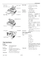
2.2.5.
Drive Unit
(1) Remove the
Right Cover
and
Left Cover
.
(Refer to 2.2.3.2.)
(2) Remove the
Control Panel Unit
. (Refer to
(3) Remove 4
Screw
(Y3).
(4) Remove the
Front 2 Cover
(614).
(5) Release the
Harnesses
from the Harness
Clamps.
(6) Remove 3
Screws
(Y3).
(7) Remove the
Support 1 Bracket
(709).
(8) Remove 4
Screws
(U1) and 1
Screw
(T9).
(9) Remove the
Solenoid Assembly
.
Summary of Contents for Panafax UF-7000
Page 9: ...Table of Contents 9 Schematic Diagram 303 10 1 General Circuit Diagram 303 ...
Page 122: ...122 UF 7000 8000 APR 2007 Ver 2 1 UF 7100 8100 Sensor and Switch Location ...
Page 304: ...304 APR 2007 Ver 2 1 UF 7000 8000 UF 7100 8100 memo ...
Page 320: ...memo ...
Page 336: ...memo ...
Page 373: ...memo ...
Page 374: ...DZZSM00287 ...