background image

9

3.4.

Safety Lock/Circuit Breaker Protection

Summary of Contents for MX-AC400WUA

Page 1: ...tic jar with Filter Unit 10 3 6 How to Clean 12 4 Troubleshooting Guide 13 5 Disassembly and Assembly Instructions 16 5 1 Rubber Cap Connector U lower 16 5 2 Bottom Plate 16 5 3 Power Cord U Circuit Breaker 17 5 4 Switch Complete 18 5 5 Switch Complete B 18 5 6 Motor Complete Upper Body 19 5 7 Blender Jar Complete PC Jar SS Jar Mill Cup Complete Chutney Jar Complete 20 5 8 Lid C Lid A Lid J 23 5 9...

Page 2: ...2 1 Safety Precautions ...

Page 3: ...3 2 Specifications ...

Page 4: ...4 3 Location of Controls and Components 3 1 Parts Identification ...

Page 5: ...5 ...

Page 6: ...6 3 2 How to Use ...

Page 7: ...7 ...

Page 8: ...8 3 3 How to Assemble Disassemble ...

Page 9: ...9 3 4 Safety Lock Circuit Breaker Protection ...

Page 10: ...10 3 5 How to Use Plastic jar with Filter Unit ...

Page 11: ...11 ...

Page 12: ...12 3 6 How to Clean ...

Page 13: ...13 4 Troubleshooting Guide ...

Page 14: ...14 ...

Page 15: ...15 ...

Page 16: ... opposite order of disassembly 5 1 Rubber Cap Connector U lower 1 Remove Rubber Cap 2 Turn the Nut clockwise and remove it 3 Pull out Connector U lower and remove Plate Washer and Lock Washer 5 2 Bottom Plate 1 Remove the 6 Tapping Screws 4x20 and remove the Bottom Plate 2 Detach the Motor Cap and Foot from the Bottom Plate ...

Page 17: ...e 2 Insulation Tubes from the Circuit Breaker remove the faston terminals of Lead Wire A U and Power Cord U and remove the Circuit Breaker Assembly Instructions Attach the Lead Wire to the Circuit Breaker and set Insulation Tubes firmly 3 Melt the solder which fixes the Lead Wire Black on Switch Complete B and remove the Power Cord U ...

Page 18: ...he solder and detach the Lead Wire Yellow Blue Red from the Motor Complete 3 Remove the Screw 4x20 and remove the Switch Com plete 5 5 Switch Complete B 1 Melt the solder and detach the Lead Wire Black from the Motor Complete 2 Remove the Screws 4x20 and remove Switch Complete B ...

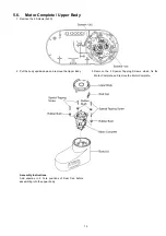
Page 19: ...x20 2 Put the body upside down and remove the Upper Body 3 Remove the 4 Special Tapping Screws which fix the Motor Complete and remove the Motor Complete Assembly Instructions Add vaseline in 2 hole positions of Seal Cap before assembling into the upper body ...

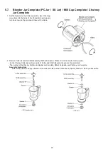
Page 20: ...out the blade 2 Remove Cutter assemble Shaft assembly Washer B Spacer Washer C and Connector Insert upper As the Chutney Cutter assembly consists of Cutter and Shaft integrally they cannot be separated The number of the Washer B differs in Blender Jar Complete Millcut Complete and Chutney Jar Complete Assembly Instructions Refer to the picture and pay attention to the order and the number of Washe...

Page 21: ...21 3 Remove 4 pcs of M4 nuts and the trust tapping screw fixing Handle to Jar Cup in order to disassemble Blender Jar assembly Mill Cup assembly or Chutney Jar assembly ...

Page 22: ... be in alignment with the holes a of Cutter Base Cover c Cutter Base Packing for SS Jar Mill Cup Chutney Jar is to be set in the direction of Cutter Base Packing rib side up d After assembling PC Jar Mill Cup Chutney Jar fill the Jar Cup with maximum quantity of water Refer to Specifications Page 3 keep it for 24 hrs and confirm no water leakage In case of water leakage reassem bly Jar Cup in acco...

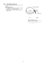
Page 23: ...asket C Gasket A from part a of Lid C Lid J Lid A Assembly Instructions a Pay attention to the orientation of Gasket C Gasket A Assemble it in the correct orientation b Apply cornstarch on Gasket C Gasket A after assem bling it into Lid ...

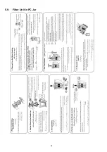
Page 24: ...24 5 9 Filter Unit in PC Jar ...

Page 25: ...e is connected with medium speed switch terminal red wire is connected with maximum speed switch terminal Motor black wire is connected to power cord black wire Power cord green wire is connected to motor body for earth and Red wire is connected to circuit breaker One end of the lead wire is connected to the circuit breaker and the other end is connected with switch ...

Page 26: ...26 6 2 Wiring diagram ...

Page 27: ...27 7 Exploded View and Replacement Parts List 7 1 MX AC400 PARTS LOCATION ...

Page 28: ...18C60000 Lock Washer 1 24 AVB99 1251 Connector U lower 1 25 AVB06 193 H0 Upper Body 1 26 AVB18 193 Seal Cap 1 27 AVM99 193 Motor U 1 28 VJ03 125 Special Tapping Screw 4 29 AVB12 125 Rubber Bush 4 30 AVB98Y224 Body U 1 31 AVY03 193 Caution Label A 1 32 AVY02 151 Caution Label 1 33 AVB11 125 Tapping Boss 2 34 AVN23 193 Switch Complete B 1 35 AVN03 158 Switch Complete 1 36 AVP97 193 Lead Wire A U 1 3...

Page 29: ...a 1 76 AVE56 124 W0 Fruit Pusher 1 SMALL STANDARDIZED METAL PARTS A XNG5B Nut 1 B XWG5 Washer Plate Washer 1 C XYN4 C10 Screw 1 D XTN4 20B Tapping Screw 11 E XST4 8VW Screw 3 F XNG4BVW Nut 16 G XTT4 12BVW Plus Truss Tapping Screw 1 PACKING SPECIFICATIONS AVZ01Y224 Inner Carton 1 AVZ03 193 Bottom Pad A 1 AVZ06 124 Bottom Pad B 1 AVZ02 124 Top Covering Pad 1 AVZ05 124 Pad for Chutney cup 1 AVZ04 193...

Page 30: ...30 7 3 MX AC400 PACKING INSTRUCTION ...

Reviews: