Control specification
1.
Temperature control
(1) Outline
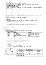
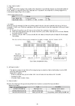
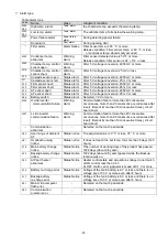
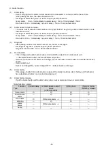
This unit controls two comp.s on the H side and the L side in cooperation, and controls the temp. inside
the refrigerator to the set temp. (two-way freezing).
Furthermore, since the two comp.s are of inverter type and the number of revolutions can be changed,
PID control is used in the vicinity of the set temp. inside the compartment.
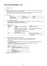
(2)
Setting
(
user
)
Item
Set range
Default
Chamber temp.
-90
℃
~
-50
℃
-80
℃
Compressor delay
3 min
~
15 min
3 min
(3)
Restrict of compressor starting
・
Immediately after turning on the power supply or immediately after recovery from power failure, do not
start the compressor for the compressor delay time.
・
When stopping the compressor, do not start for 3 minutes.
(4)
Compressor mode
Name
Action
Condition
NORMAL
Temperature control by NORMAL
MODE
During normal operation
ON
Basically it is the same as NORMAL
model, and both comp.s are always
ON without temp. control. The
rotational speed is maintained constant
speed operation
During security operation (chamber
temp. unknown)
OFF
Both comp.s are always OFF
Demo mode, Power failure
Security operation (comp. protection
temp. alarm)
(5)
Condition and Priority of comp. operation mode
・
The condition and the priority of comp. operation mode as following bellow table.
When the state overlap, the comp. operation mode is determined by the priority.
For each state
、
・
For the power failure and demo mode, both are same comp. running operation mode. So, they are
coedited as same level.
・
Test Program and capirariy heater control are not run within being higher priority condition.
If higher priority condition starts, these are stopped.
Priority
Condition
High
Power failure, Demo mode
Security operation
(
There is also priority in
this
)
Test Program
Capi heater control
Low
Other than those above
Comp.Control in service menu
-25-
Summary of Contents for MDF-DU702VH
Page 8: ...Dimension MDF DU502VH 5 ...
Page 9: ...MDF DU702VH 6 ...
Page 17: ...Wiring Diagram 14 ...
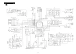
Page 18: ...main Circuit Diagram 15 ...
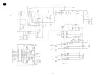
Page 19: ...power 16 ...
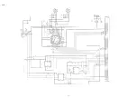
Page 20: ...USB 17 ...
Page 73: ...WIRING YG Y Y GR B G W W W Y G R BL Y W R R BL R OR B BL R OR B Y W Y G Y G R BL 70 ...

