


133
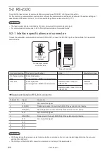
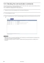
5-3-3 Connecting to external control devices and its setting sample
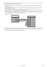
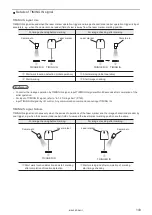
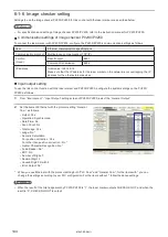
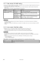
Connect the two or more laser markers and an external device via a HUB or a router:
Use a HUB (or a rooter) that supports 100BASE-TX/10BASE-T and a cable of Category 5 or higher for the connection.
HUB (or rooter)
External controller (PC, etc.)
Laser marker controller
(Several units connected)
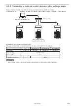
Example of communication system settings:
Set a separate IP address not to overlap between the laser marker and PC on the network.
PC
Laser marker A
Laser marker B
Laser marker C
IP address
192.168.1.10
192.168.1.5
192.168.1.6
192.168.1.7
Subnet mask
255.255.255.0
Default gateway
None
Command control port
—
9094
ンㄆㄇㄆㄓㄆㄏㄆ
• When the laser marker is connected the external control device one to one, no HUB is necessary.
ME-LPRF-SM-11
Summary of Contents for LP-RF Series
Page 17: ...1 Product Overview ME LPRF SM 11...
Page 34: ...2 Laser Marker Installation ME LPRF SM 11...
Page 57: ...3 Operation Method ME LPRF SM 11...
Page 81: ...4 External Control Using I O ME LPRF SM 11...
Page 126: ...5 External Control by Communication Commands ME LPRF SM 11...
Page 135: ...6 Link Control with External Devices ME LPRF SM 11...
Page 160: ...7 Maintenance ME LPRF SM 11...
Page 186: ...Troubleshooting ME LPRF SM 11...
Page 214: ...Index ME LPRF SM 11...
Page 216: ...216 USB 32 55 W Warning 205 ME LPRF SM 11...
Page 217: ......


