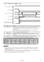


131
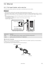
5-3 Ethernet
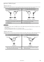
5-3-1 Port specifications and connection
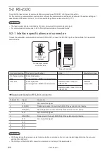
To control the laser marker by Ethernet communication, use an Ethernet port on the controller.
ンㄆㄇㄆㄓㄆㄏㄆ
• The Ethernet port of this product is compatible with both straight cable and cross cable.
• Although the maximum length of cables connecting devices permitted by the standards of Ethernet is 100 m, in order to
prevent communication failure due to noise or breakdown of the device, it is recommended to keep the length to 10 m or
less.
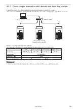
• The Ethernet port can be connected with the following devices simultaneously via a HUB or a router.
• PC configuration software
• External device for communication command control (PLC and PC for control)
• Specific image checker
Rear of controller
On the laser marker controller side
RJ-45 8-pole connector
AUTO-MDIX compatible
Orange LED
Green LED
Light up color
Description
Green
The indicator lights up while connected normally. It blinks during communication.
Orange
Lights up only when the baud rate is 100 megabits/sec.
⿎
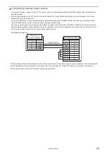
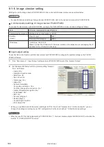
LAN cable connection
When you connect a LAN cable to the Ethernet port, attach the ferrite core included to a position as close as possible to
the Ethernet port on the LAN cable controller side.
Turn the LAN cable 3 times around the ferrite core as shown below figure.
Ferrite core
LAN cable
Laser marker controller
ME-LPRF-SM-11
Summary of Contents for LP-RF Series
Page 17: ...1 Product Overview ME LPRF SM 11...
Page 34: ...2 Laser Marker Installation ME LPRF SM 11...
Page 57: ...3 Operation Method ME LPRF SM 11...
Page 81: ...4 External Control Using I O ME LPRF SM 11...
Page 126: ...5 External Control by Communication Commands ME LPRF SM 11...
Page 135: ...6 Link Control with External Devices ME LPRF SM 11...
Page 160: ...7 Maintenance ME LPRF SM 11...
Page 186: ...Troubleshooting ME LPRF SM 11...
Page 214: ...Index ME LPRF SM 11...
Page 216: ...216 USB 32 55 W Warning 205 ME LPRF SM 11...
Page 217: ......


