170
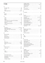
Index
A
AC power cable ……………………………………… 35
Air filter ………………………………………………… 133
Alarm …………………………………………………… 161
Alarm Reset Switch ………………………………… 22, 43
B
Backup ………………………………………………… 144
Battery …………………………………………… 142, 146
C
Cable …………………………………………………… 35
Class 2 ………………………………………………… 17
Class 4 ………………………………………………… 17
Communication Command Control Settings ……… 75
Connecting Laser Marker …………………………… 57
Console ……………………………………………… 36, 62
Console Return Connector …………………………… 44
Controller ……………………………………………… 42
D
DIP switch ……………………………………… 44, 46, 73
Displacement Sensor ………………………………… 110
Displacement sensor input connector ………… 77, 110
Disposal ………………………………………………… 146
Dual Pointer …………………………………………… 56
E
Error Indication ………………………………………… 161
Ethernet ………………………………………………… 126
Ethernet Port …………………………………………… 44
External control ……………………………………… 70
External power ………………………………………… 95
F
Fan ……………………………………………………… 134
Fiber Cable ………………………………………… 40, 45
Frame ground terminal …………………………… 40, 59
Fuse …………………………………………………… 143
G
Galvano scanner ……………………………………… 141
Guide Laser ………………………………………… 17, 56
H
Head …………………………………………………… 40
Heat sink ……………………………………………… 41
I
Input/Output Terminal ………………………………… 80
Input Rating and Input Circuit ……………………… 92
Input signal …………………………………………… 81
Input Terminal ………………………………………… 45
Installation Method …………………………………… 49
Installation Space ……………………………………… 54
Interlock Connector ……………………………… 25, 115
Interlock System ……………………………………… 26
Internal power ………………………………………… 95
I/O ……………………………………………………… 77
I/O Connector ………………………………… 45, 78, 86
I/O terminal block ……………………………………… 78
K
Key Switch ……………………………………………… 42
L
Labels …………………………………………………… 23
Laser emission port …………………………………… 130
Laser Gate …………………………………… 22, 117, 141
Laser Gate Cable ……………………………………… 35
Laser gate cable connector ……………………… 41, 45
Laser Gate Terminal ………………………… 22, 45, 117
Laser oscillator ………………………………………… 136
Laser Output Optimize ……………………………… 137
Laser Pointer Emission Port ………………………… 40
Laser Pumping Switch………………………………… 43
Laser safety manager ………………………………… 20
Laser Stop ……………………………………… 22, 25, 97
M
Marking Center Position ……………………………… 55
Marking Field ………………………………………… 55
Max. Output …………………………………………… 17
Model …………………………………………………… 28
Monitor and Mouse …………………………………… 63
N
NHZ …………………………………………………… 17
NOHD …………………………………………………… 17
O
One-shot time ………………………………………… 75
Operation procedure ………………………………… 71
Optional items ………………………………………… 29
Origin point recovery ………………………………… 121
Outer Dimensional Drawing ………………………… 33
Output Rating and Output Circuit …………………… 93
Output signal operation ……………………………… 83
Output Terminal ……………………………………… 45
P
Package ………………………………………………… 38
Power Connector …………………………………… 40, 45
Power Supply ………………………………………… 59
Power Terminal ………………………………………… 45
Protective conductor terminal …………………… 45, 59
Protective enclosure ………………………………… 19
Protective goggles …………………………………… 19
Pulse Cycle …………………………………………… 17
Pulse duration ………………………………………… 17
R
ME-LPM-SSM-10
Summary of Contents for LP-M Series
Page 16: ...16 MEMO ME LPM SSM 10...
Page 27: ...27 Chapter 1 Specification ME LPM SSM 10...
Page 37: ...37 Chapter 2 Preparation ME LPM SSM 10...
Page 69: ...Chapter 3 Connection for External Control ME LPM SSM 10...
Page 128: ...Chapter 4 Maintenance ME LPM SSM 10...
Page 148: ...Troubleshooting ME LPM SSM 10...
Page 169: ...Index ME LPM SSM 10...
Page 172: ...172 MEMO No 9000 0066 34V ME LPM SSM 10...
Page 173: ...No 9000 0066 34V...


