– 88 –
Chapter 5 Basic Operations — Memory
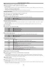
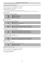
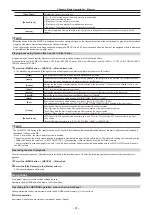
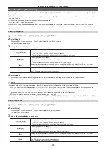
[ON]
Made the target for recalling.
[OFF]
Not made the target for recalling.
4
Select an item in [Clip1], [Clip2] in the [Detail Clip] column.
[ON]
Made the target for recalling.
[OFF]
Not made the target for recalling.
5
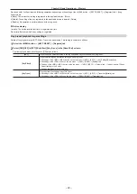
Select an item in [AUX Sel1] to [AUX Sel5] in the [Detail AUX] column.
f
Select items from [AUX1] to [AUX16].
To select all AUX buses, select [All] in [AUX Sel1].
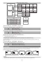
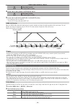
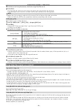
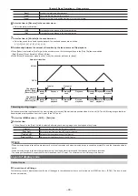
EMEM LINK function
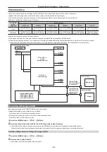
Select the <EMEM LINK> button in the transition area to execute a transition according to the pattern registered in the event memory. The next
transition operation by the fader lever or the <AUTO>/<CUT> buttons becomes the operation of the event memory.
f
Pause set using the mark is disabled.
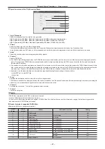
Amount of transition
PGM-A
PST-B
Event memory
Ex) Events 1 to 3
Event 1
Playback
Event 1
Playback
Event 1
Playback
Reverse
playback
Event 1 Event 2
Event 2
Event 2
Event 3
Event 3
Event 1
Event 1
Event 1
@
@
NOTE
t
The target to be played back by EMEM LINK is the background transition for ME (ME1, ME2) which is controlled by the ME line to which the
corresponding <EMEM LINK> button belongs. KEY is not played back.
t
DSK, AUX, Clip, CBGD, and XPT are not played back with the EMEM LINK operation.
t
The register memory last played back for ME (ME1, ME2) of the EMEM LINK target is played back with the fader lever.
The register memory can be changed in the multi-selection panel area before the fader lever operation. The register memory to be played back with
EMEM LINK lights in red in the multi-selection panel area.
t
When the register memory is ready for playback by the fader lever, the <EMEM LINK> button lights in the High tally color.
t
If the register memory cannot be played back by the fader lever, such as when the register memory to be played back is not selected, the <EMEM
LINK> button lights in the Low tally color.
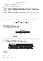
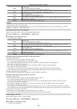
Macro memory
The macro memory is a function to record and play back a series of operations performed on the Control Panel and Menu Panel.
It enables recording and playback of a more detailed range including functions which are not covered by the shot memory and the event memory (such
as input setting and output setting).
Recorded macros can be played by pressing the macro bus crosspoint buttons or a specific button where macro is attached.
@
@
NOTE
t
Recorded macros can be registered in 81 register memories (9 pages×9 memories).
t
Each register memory of a macro has the capacity of 127 KB, and can store approximately 3000 steps of operations depending on the operation.
t
When an operation that takes time to process is recorded, next operation may not playback correctly. Insert a delay between the two operations as
necessary. For the procedure to insert a delay, refer to “Recording to the work memory”.
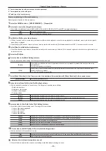
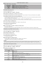
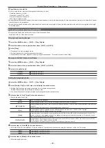
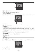
Status displays
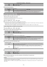
The [MACRO] indicator at the top of the menu panel turns red when a macro is being recorded and turns green when a macro is being played back.
1
Select the <MEM> button
→
[MACRO]
→
[Macro] tab.
2
Check the [Status] column display.
[Rec]
[Rec] is displayed during macro recording.
This has a blank display except during macro recording.
[Play]
The name of the macro currently playing is displayed during macro playback.
This has a blank display except during macro playback.
[Pause]
The name of paused macro is displayed when the macro playback is paused.
The display other than when the macro playback is paused will be blank.
Summary of Contents for Live Production Suite Series
Page 5: ...Please read this chapter and check the accessories before use Chapter 1 Overview ...
Page 11: ...This chapter describes installation and connection Chapter 2 Installation and Connection ...
Page 50: ...This chapter describes menu operations Chapter 5 Basic Operations ...
Page 113: ...This chapter describes the configuration of operations Chapter 7 Configuring Operations ...
Page 122: ...This chapter describes how to operate system menus Chapter 8 System Menu ...
Page 136: ...This chapter describes plug in functions Chapter 9 External Interfaces ...
Page 140: ... 140 Chapter 10 Specifications Dimensions Dimensions of the XPT Unit AV LSX10 Unit mm inch ...
Page 141: ... 141 Chapter 10 Specifications Dimensions Dimensions of the ME Unit AV LSM10 Unit mm inch ...
Page 153: ...This chapter describes the setting menu table and terms Chapter 11 Appendix ...
Page 176: ...Web Site https www panasonic com Panasonic Corporation 2020 ...

