


– 119 –
Chapter 7 Configuring Operations — Setting the operation mode
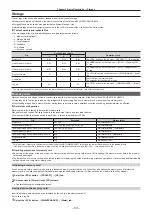
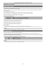
FTB (Fade to Black)
For DSKPGM1 and DSKPGM2 outputs, fade out from the program image to the black background screen, and fade in from the black ground screen
to the program image. While the settings and transition are performed by the menu, use the macro memory to assign to certain buttons to execute
transition.
1
Select the <OPR> button
→
[OTHER SETTINGS]
→
[Transition] tab.
2
Select an item in [Source] in the [FTB] column.
f
Select the image for fading out.
[Still1], [Still2]
Uses still image video memory (Still1, Still2).
[Clip1], [Clip2]
Uses moving image video memory (Clip1, Clip2).
[CBGD1], [CBGD2]
Uses the color background.
[White]
Uses the white background.
[Black]
Uses the black background.
3
Set [Time] in the [FTB] column.
f
Set the transition time.
4
Set [FTB On] in the [FTB] column.
f
When [FTB On] is selected, the screen fades out to the image selected in the step
at a specified transition time.
If [FTB On] is selected when the image selected in the step
is on the screen, the screen fades in to the program image.
If [FTB On] is selected during transition, the transition direction is reversed.
@
@
NOTE
t
If an item other than [White] or [Black] is selected in [Source] in the [FTB] column, the corresponding crosspoint buttons will light in red while [FTB On]
is set.
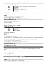
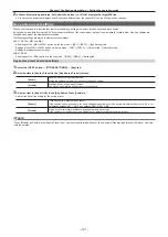
AUX1 to AUX4 bus transitions
In the AUX1 to AUX4 buses, MIX transition is available.
1
Select the <OPR> button
→
[OTHER SETTINGS]
→
[Transition] tab.
2
Select an item in [AUX1] to [AUX4] in the [AUX Trans] column.
[OFF]
Disables the MIX translation.
[ON]
Enables the MIX translation.
3
Set [AUX1] through [AUX4] in the [Trans Time] column.
f
Set the transition time.
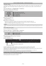
r
AUX bus transition operation
CG
3V
CG
4V
STIL
1V
STIL
2V
V5
V6
CG
1V
CG
2V
ME1
ME2
ME3
ME4
CLIP
3V
CLIP4
V
BC1
BC2
DSK4
F/S
DSK3
F/S
DSK2
F/S
DSK1
F/S
STIL
3V
STIL
4V
CLIP
1V
CLIP
2V
V1
V2
V3
V4
C9
C10
C11
C12
C9
C10
C11
C12
C9
C10
C11
C12
AUX
7/8
AUX
5/6
AUX
3/4
AUX
1/2
AUX
17/18
AUX
15/16
AUX
13/14
AUX
11/12
AUX
9/10
USK3
F/S
USK2
F/S
USK1
F/S
AUX
23/24
AUX
21/22
AUX
19/20
USK4
F/S
MCRO
DISP
VMEM
F/S
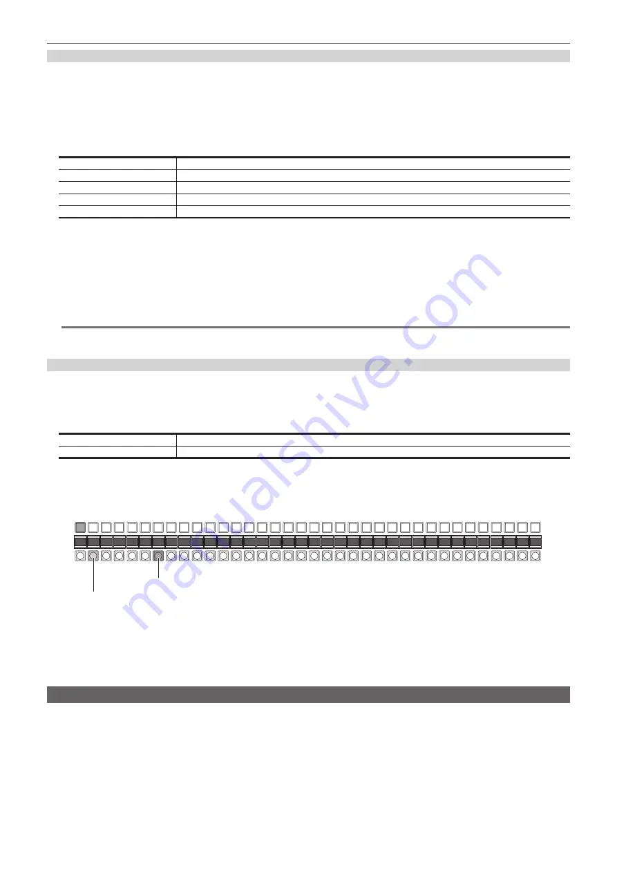
Lights in the Preset tally color
Blinks in the Low tally color (during transition)
Set [AUX1] to [AUX4] to [ON] in the [AUX Trans] column, then select sources with the relevant AUX bus crosspoint buttons.
At this time, the MIX transition is performed at the transition time specified in [AUX1] to [AUX4] in the [Trans Time] column.
During transition, KEY crosspoint buttons denoting the transition source lights in the Preset tally color, and the KEY bus crosspoint buttons denoting the
transition target source lights in the Low tally color.
When the transition is completed, the transition source button goes off, and the transition target button lights in the Low tally color.
When another signal is selected during transition, the transition processing continues from that midway point.
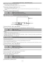
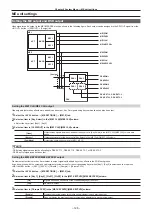
Switching the ME area in the Control Panel AV-HS60C2/AV-HS60C4
Switch the ME1 and ME2 in the Control Panel AV-HS60C2/AV-HS60C4.
f
The following figure shows the area that can be switched.
Summary of Contents for Live Production Suite Series
Page 5: ...Please read this chapter and check the accessories before use Chapter 1 Overview ...
Page 11: ...This chapter describes installation and connection Chapter 2 Installation and Connection ...
Page 50: ...This chapter describes menu operations Chapter 5 Basic Operations ...
Page 113: ...This chapter describes the configuration of operations Chapter 7 Configuring Operations ...
Page 122: ...This chapter describes how to operate system menus Chapter 8 System Menu ...
Page 136: ...This chapter describes plug in functions Chapter 9 External Interfaces ...
Page 140: ... 140 Chapter 10 Specifications Dimensions Dimensions of the XPT Unit AV LSX10 Unit mm inch ...
Page 141: ... 141 Chapter 10 Specifications Dimensions Dimensions of the ME Unit AV LSM10 Unit mm inch ...
Page 153: ...This chapter describes the setting menu table and terms Chapter 11 Appendix ...
Page 176: ...Web Site https www panasonic com Panasonic Corporation 2020 ...