background image

Page 1-58

Check Every 1500 Hours (Once Three Months)

1-7-4

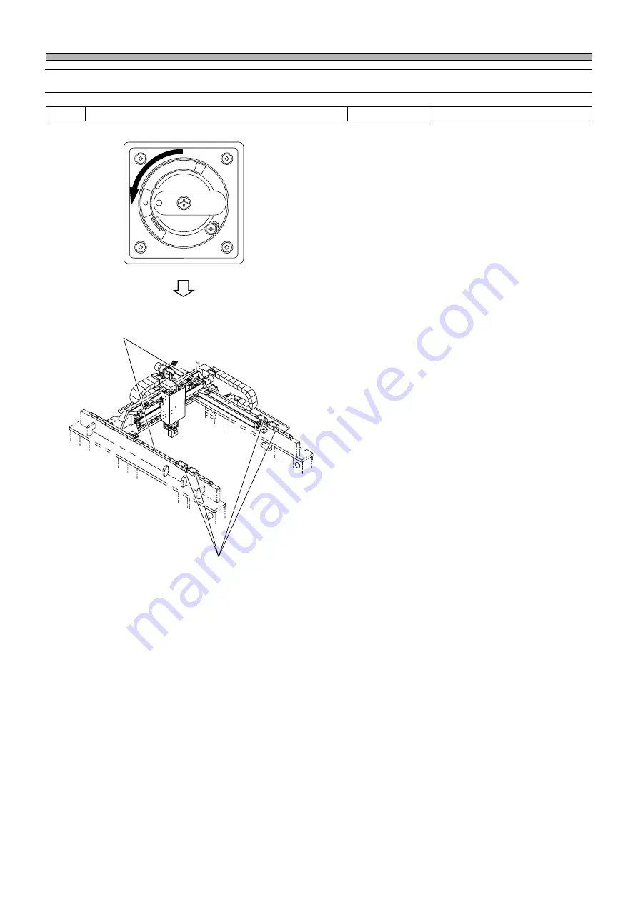
Cleaning and Lubricating the Linear Bearing of Squeegee Axis

1.

Turn off the power.

2.

Open the front and rear safety covers.

3.

Clean and lubricate the linear bearing.

1.Linear bearing of squeegee axis

Lubricate the grease nipple.

Tools

Required time

5 to 10 minutes

1E4C-E-MMA01-A09-00

Linear way of recognition unit and squeegee head

Linear bearing of squeegee axis

REL

EA

SE

TR

IP

O

F

F

ON

RE

S

E

T

160HC1AA

Summary of Contents for KXF-1E4C

Page 1: ...KXF 1F4C Thank you for purchasing SP28P the high speed screen printer Before placing the machine in service be sure to read the instruction manual for proper usage After that store it carefully and it if necessary 1E4C E MMAB 0013 High Speed Screen Printer SP28P ...

Page 2: ......

Page 3: ...ty Saga Japan TEL 81 942 84 2644 FAX 81 942 84 2636 For Service and Supply of Spares in Europe you may contact Panasonic Europe Continental Europe PFSE Panasonic Factory Solutions Europe Winsbergring 15 22525 Hamburg Germany Phone number 0049 0 40 85386 321 Fax number 0049 0 40 85386 332 United Kingdom PFSE Panasonic Factory Solutions Europe Panasonic House Willoughby Road Bracknell Berks RG12 8 F...

Page 4: ...5 1 n o i t c e r i d g n i t a t o r n i e c n a r a e l C m m 3 o t m m 5 0 n o i t a r e l e c c a y t i c o l e v e s a e l e r k s a M l o r t n o c y t i c o l e v m r o f i n u l o r t n o c d e e p s h g i h l o r t n o c e l p i t l u m l o r t n o c n o i t a r e l e c c a s m m 1 0 s m m 5 o t s m m 1 0 y t i c o l e v l a n i m r e t s m m 5 0 0 y t i c o l e v l a i t i n I s m m 0 1 ...

Page 5: ...nd person in charge The production data of the line including this machine are programmed on PT Refer to the instruction manuals accompanied with PT Operating manual Manuals of this equipment This manual is for the persons who maintain this equipment It de scribes simple inspection adjustment and replacement of consumable parts Troubleshooting is also described Maintenance manual The assembly of e...

Page 6: ...4 1E4C E MMA00 B01 00 MEMO ...

Page 7: ...1 2 3 4 5 Maintenance Maintenance Manua Manual l 1E4C E MMA00 A02 14 SAFETY PRECAUTIONS REGULAR MAINTENANCE MACHINE PARAMETER ADJUSTING THE MACHINE CONDITION SOLUTIONS FOR ERROR TROUBLE SHOOTING APPENDIX ...

Page 8: ...Solvent Dispensing Nozzle 1 29 1 4 3 Cleaning the Filter of the Temperature Controller Option 1 31 1 4 4 Cleaning the Printing Unit Option 1 32 1 5 Check Every 560 Hours Once a Month 1 36 1 5 1 Checking the Board Transfer Belts 1 36 1 5 2 Cleaning and Lubricating the X Y Table Ball Screw 1 39 1 5 3 Checking the Air Pressure of Squeegee Rising 1 41 1 5 4 Checking the MR Unit 1 42 1 5 5 Checking the...

Page 9: ...ter 2 2 2 1 1 Origin Offset 1 2 3 2 1 2 Origin Offset 2 2 3 2 1 3 Network Setting Only for PT Specifications 2 4 2 1 4 Status Indicator 2 5 2 1 5 Judgment Value 2 5 2 1 6 Camera 2 6 2 1 7 Other Offset 2 6 2 1 8 Operation Parameter Setting 2 7 2 1 9 Option Setting 2 7 2 1 10 Data Check 2 8 2 2 Machine Maintenance 2 9 2 2 1 Routine Maintenance 2 9 2 2 2 Changing Consumable Parts 2 11 2 2 3 Machine I...

Page 10: ...File Operation Errors in Saving 4 10 4 2 Check and Solutions 4 11 4 2 1 Air Pressure Drops 4 11 4 2 2 Pre Process Production End 4 11 4 2 3 Thermal Trip Detection Blower 4 12 4 2 4 Power Box Fan Motor 4 12 4 2 5 Temperature Sensor 4 13 4 2 6 Lift Axis Brake off Under Axis Brake off 4 13 4 2 7 Thermal Trip Detection Vacuum Pump 4 14 4 2 8 PCB Recognition Error 4 15 4 2 9 Returning to Origin Error F...

Page 11: ...RAM SP28P DH DHU B 3 LOAD WIRING DIAGRAM SP28P DU DHU Appendix C CONTROL BOX DIAGRAM C 1 CPU BOX C 2 POWER BOX C 3 400V TRANS BOX SP28P DU DHU Appendix D JUNCTION BOARD D 1 EC14EX D 2 EC55CX D 3 RL12CX Appendix E SET UP DIAGRAM Appendix F WHOLE CONNECTION DIAGRAM SP28P DU DHU Appendix G AIR CIRCUIT DIAGRAM 1E4C E MMA00 A02 03 ...

Page 12: ...10 1E4C E MMA00 A02 01 MEMO ...

Page 13: ...gs are only some examples of the symbolic indications This indication refers to a situation which is considered that there is imminent danger of death or serious injury This indication refers to a situation which is considered that there is a possibility of death or serious injury This indication refers to a situation which is considered that there is a possibility of only injury or physical damag...

Page 14: ...rve 1E4C E XXA00 A03 01 L06EB DO NOT OPEN THE COVER WHEN OPER ATING You will have serious injury if you touch the active part inside DANGER L02E DO NOT TOUCH AC TIVE PART WHEN OPERATING You will have serious injury if you touch the active part ...

Page 15: ...ur There are two emergency stop buttons Pressing any one of them stops operation Press the nearest one Remove the cause of the danger or abnormality then re start the machine To reset the emergency stop button pull it forward SP28P DH D The explanation by using SP28P DH illustration M33E 2B 1E4C AA00 E MERGEN C Y STOP E MERGEN C Y STOP E M E RGENC Y STO P 1E4C E XXA00 A03 00 WARNING 2 Emergency st...

Page 16: ...r There are two emergency stop buttons Pressing any one of them stops operation Press the nearest one Remove the cause of the danger or abnormality then re start the machine To reset the emergency stop button pull it forward SP28P DHU DU The explanation by using SP28P DH illustration M33E 2B 1E4C AA00 E MERGEN C Y STOP E MERGEN C Y STOP E M E RGENC Y STO P 1E4C E XXA00 A03 00 WARNING 2 Emergency s...

Page 17: ... struck by an electric shock There are three levels of procedure shown below for each kind of work For repairing the control box Cutting off the power suly of the machine This is used to turn off power supply normally Power supply OFF For replacing the control part such as the sensor For disassembling or replacing parts For changing production board and daily inspection Servo switch OFF For placin...

Page 18: ...ck by an electric shock There are three levels of procedure shown below for each kind of work For repairing the control box Cutting off the power suly of the machine This is used to turn off power supply normally Power supply OFF For replacing the control part such as the sensor For disassembling or replacing parts For changing production board and daily inspection Servo switch OFF For placing or ...

Page 19: ...2 WARNING L13EB DO NOT DISABLE SAFETY SENSOR You will have serious injury by active part if you disable safety sensor Do not remove the sensor put any objects in or turn off the switch so that the safety sensor work properly and effectively No open flame E PC010401 ...

Page 20: ...improperly and injure you Either carry out training by yourself or consult the manufacturer DO NOT PLACE YOUR HANDS OR BODY INSIDE ACTIVE PART OF THE MACHINE WHEN IT IS IN A SINGLE STOP OR CYCLE STOP CONDITION The machine has been stopped only temporarily You may be injured if the sensors are actuated and the machine moves unexpectedly Turn OFF the servo switch before placing your hands or body in...

Page 21: ...e caused by defective insulation because of moisture Pull out the power plug and wipe off dirt with dry cloth If the machine is not going to be used for a long period turn off the breaker connected with the machine M86E DO NOT DAMAGE POWER AND OTHER CORDS OR PLUGS Damaged cord and plug may cause electric shock short circuit or fire Hold the plug when plugging in or unplugging Cord and plug repairs...

Page 22: ... tool left inside Before operating the ma chine verify that no tools are left inside M26EB BE CAREFUL OF THE PNEUMATIC PRES SURE UNIT You may stumble over the pneumatic unit break the glass and be injured IPA ISOPROPYL AL COHOL USE ONLY The corrosion damage to the hose may cause the machine to catch fire L28EB 1E4C E XXA00 A03 01 CAUTION M20EB DO NOT BLOCK OFF THE OUTLET OR IN LET OF THE FAN The t...

Page 23: ...ion manuals when using solder pastes M74E BEFORE PERFORMING AUTOMATIC WIDTH ADJUSTMENT BE SURE TO VERIFY NO BOARDS OR OTHER OBJECTS ARE ON THE CONVEYOR Boards or other objects may drop from the con veyor causing damage to the boards or the ma chine If there are any boards or other objects on the conveyor turn OFF the servo switch and remove them M36E 1E4C E XXA00 A03 01 CAUTION DO NOT DISAS SEMBLE...

Page 24: ...OL Isopropyl alcohol is harmful to the human body Wear the mask to avoid organic odor when using isopropyl alcohol M84EB ONLY USE RECOM MENDED CLEANING SOLVENT Use of other cleaning solvents may corrode the hose resulting in causing the machine to catch fire L37E 1E4C E XXA00 A03 01 CAUTION ...

Page 25: ...is a label for ensuring the safe machine use If you do not observe it there is a risk of human injury or damage to property Front side of warning label indicated positions 1E4C 447E Rear side of warning label indicated positions 1E4C AB00 The labels for safety pasted on the product Label part No ...

Page 26: ...ning labels This is a label for ensuring the safe machine use If you do not observe it there is a risk of human injury or damage to property Front side of warning label indicated positions 1E4C 447E The labels for safety pasted on the product Label part No Inside the front cover ...

Page 27: ...de the front cover Inside the front cover Left side of clamping pressure gauge box SP28P D Warning labels This is a label for ensuring the safe machine use If you do not observe it there is a risk of human injury or damage to property Front side of warning label indicated positions Label part No Internal illumination Option ...

Page 28: ...SP28P DH Warning labels This is a label for ensuring the safe machine use If you do not observe it there is a risk of human injury or damage to property Front side of warning label indicated positions 1E4C AB00 The labels for safety pasted on the product Label part No ...

Page 29: ... machine use If you do not observe it there is a risk of human injury or damage to property Rear side of warning label indicated positions 1E4C AB00 The labels for safety pasted on the product Inside the rear cover Label part No Blower Large capacity vacuum pump Option Board flattener cylinder mounting bar 1E4C 463E 1E4C 464E ...

Page 30: ...for ensuring the safe machine use If you do not observe it there is a risk of human injury or damage to property Front side of warning label indicated positions The labels for safety pasted on the product Label part No 1E4C AA00 Inside the front cover 1E4C AB00 Rear side of warning label indicated positions ...

Page 31: ...15A Option Warning labels This is a label for ensuring the safe machine use If you do not observe it there is a risk of human injury or damage to property MPA 15A is the optional unit of SP28P DH Warning label indicated positions 1E4C 003E The labels for safety pasted on the product Label part No ...

Page 32: ...N OPERATING 0 8 6 R A 1E4C E XXA00 A03 03 The labels for safety pasted on the product Label part No 0 1 J Q B feeder tables will have serious injury 0 1 J X A DANGER DO NOT TOUCH ACTIVE PART WHEN OPERATING You will have serious injury if you touch the active part Rear side of warning label indicated positions The explanation by using SP28P DH illustration 0 1 K 1 B DANGER DO NOT OPEN THE COVER WHE...

Page 33: ...HEN OPERATING 0 8 6 R A 1E4C E XXA00 A03 00 The labels for safety pasted on the product Label part No 0 1 J Q B feeder tables will have serious injury 0 1 J X A DANGER DO NOT TOUCH ACTIVE PART WHEN OPERATING You will have serious injury if you touch the active part Rear side of warning label indicated positions The explanation by using SP28P DH illustration 0 1 K 1 B DANGER DO NOT OPEN THE COVER W...

Page 34: ...achine use If you do not observe it there is a risk of human injury or damage to property Front side of warning label indicated positions The explanation by using SP28P DH illustration 1E4C AA00 1E4C E XXA00 A03 00 The labels for safety pasted on the product Label part No 0 1 J Q B feeder tables will have serious injury 1E4C AB00 0 8 F 1 A NO OPEN FLAME Solvent may catch fire Keep away from fire W...

Page 35: ...man injury or damage to property Front side of warning label indicated positions The explanation by using SP28P DH illustration 1E4C AA00 1E4C E XXA00 A03 00 The labels for safety pasted on the product Label part No 0 1 J Q B feeder tables will have serious injury 1E4C AB00 0 8 F 1 A NO OPEN FLAME Solvent may catch fire Keep away from fire WARNING 0 9 F N A WARNING DO NOT DISABLE SAFETY SENSOR You...

Page 36: ... causing the machine to catch fire SP28P D Caution labels This is a label for ensuring the safe machine use If you do not observe it there is a risk of human injury or damage to property Front side of warning label indicated positions The explanation by using SP28P DH illustration 1E4C AA00 1E4C E XXA00 A03 00 The labels for safety pasted on the product Label part No 0 1 J Q B feeder tables will h...

Page 37: ...ausing the machine to catch fire SP28P DHU DU Caution labels This is a label for ensuring the safe machine use If you do not observe it there is a risk of human injury or damage to property Front side of warning label indicated positions The explanation by using SP28P DH illustration 1E4C AA00 1E4C E XXA00 A03 00 The labels for safety pasted on the product Label part No 0 1 J Q B feeder tables wil...

Page 38: ...afe machine use If you do not observe it there is a risk of human injury or damage to property MPA 15AU is the optional unit of SP28P DHU Front side of warning label indicated positions 1E4C 003E The labels for safety pasted on the product Label part No 0 1 J Q B feeder tables will have serious injury 1E4C 004E 0 1 N C B WARNING ELECTRIC SHOCK You will have serious electric shock if you touch elec...

Page 39: ...y Switch for Maaintenance 1 Key switch for maintenance at our company This switch which is targeted for the technician belonging to our company or the commissioned maintenance technician can release all of the safety cover interlocks It is used for such an exten sive maintenance work as you cannot perform 2 Feature of key switch for maintenance at our company It is dangerous to use this maintenanc...

Page 40: ...4C 448E 070LC0AA Conveyor Cover Two plates are attached to the Y axis cover 1 ATTENTION DON T PUT YOUR HANDS ON THIS COVER 1E4C E XXA00 A04 06 1E4C AB00 Do not open the cover during operation Push the and check the machine stopped before this STOP STOP Do not move the unit by holding the Lodacell Holding the Lodacell may damage itself Do not move the unit by holding the camera Holding the camera m...

Page 41: ...eat care Use unused cleaning solvent Do not use water or the mixture of water and other cleaning solvent as the cleaning solvent Rust or change in quality of cleaning solvent may block piping and damage the machine When using cleaning solvent other than ethyl alcohol and IPA consult us If the use of another cleaning solvent causes a problem we will not repair under warranty Wear the mask to avoid ...

Page 42: ...ase inside the blower will cause damage to bearings and the like resulting in the failure of the blower Judgment criterion for filter clogging As the judgment criterion for the filter clogging the amount of exhaust from the blower vent be comes less On the order of 5 m s wind speed Replacement of filter If the filter is clogged replace it with a new one immediately There is a possibility that only...

Page 43: ...d or may not be loaded by improper handling Make sure to back up the data on a disk to protect against the loss of data To back up the data make another copy disk of the same contents 2 Write Protection The stored data may be mechanically protected from accidental erasure or rewriting Write protection may be set or disabled by sliding the write protect tab located at the lower part of the floppy d...

Page 44: ... in areas exposed to the following conditions Do not apply excessive force to the disk Do not place heavy objects on the disk Automatic shutter The automatic shutter should not be opened Do not touch the magnetic circu lar disk inside Refrain from smoking drinking and eating close to the disk Any loose labels should be re placed with new ones Do not place the disk in the vicinity of a motor CRT or...

Page 45: ... this machine indicates the model name and produc tion number 1E4C AB00 SP28P DH SP28P DHU 1E4C E XXA00 A04 02 1E4C AB00 Actual numbers are shown on the plate instead of Actual numbers are shown on the plate instead of SP28 DH KXF 1E4C SP28 DHU KXF 1F4C ...

Page 46: ...e 34 1E4C E XXA00 A04 02 SERIAL PLATE SP28P D Actual numbers are shown on the plate instead of SP28P DU Actual numbers are shown on the plate instead of 1D4C AC00 1B4C AB03 SP28 D KXF 1B4C SP28 DU KXF 1D4C ...

Page 47: ... 1E4C 003E Temperature Control Unit MPA 15A Temperature Control Unit MPA 15AU 1E4C 003E Actual numbers are shown on the plate instead of Actual numbers are shown on the plate instead of MPA 15 KXF 10TC SERIAL PLATE MPA 15U KXF 11TC ...

Page 48: ...chips and oil discharge when the air is coming out use safety glasses for protection Position to use the air spring Position to drill the air spring 1B4C 442E 15 mm to 20 mm Hole 1E4C AA00 1D4C 406E Bolt with hexagonal hole Air spring ABOUT DISPOSAL OF COMPONENTS CONTAINING MERCURY NOTICE This product has a fluorescent lamp that contains a small amount of mercury It also contains lead in some comp...

Page 49: ...used for description Title Actual operation Supplementary description Operating step number These show operation flow This shows the reference item This shows the operation by engineers This shows the operation by operators This shows pressing a key on the touch panel This means pressing UNLOCK and then START on the operating panel within 2 seconds This means pressing the key B while holding the k...

Page 50: ...PERATION SP28P DH Front view Rear view External view Features Front view Rear view 1B4C AB03 SP28P D SP28P DHU Front view Rear view 1E4C AA00 1E4C AB00 Front view 1D4C AB00 Rear view 1D4C AC00 SP28P DU For further information about the specification see 1 3 Equipment Specification in the Operating Manual 1E4C AB00 1E4C AA00 1B4C AA03 Standard specification CE specification 1E4C E XXA00 A04 00 ...

Page 51: ...o inform the operator Carrying out maintenance based on the run time enables the machine to run under more stable conditions This chapter is constructed as follows 1 1 Outline of Maintenance The renewal of the maintenance period and history and the list of items for each period and the unit is shown 1 2 Lubricating How to use the grease gun and the points of greasing are described 1 3 to 1 9 Detai...

Page 52: ...n yellow on the Main Menu screen After the periodic time it blinks in red The left screen is displaying three items together to indicate the position on the screen 1 Press Machine parameter Machine parameter menu appears 2 Press Machine mainte The Machine maintenance menu screen appears Run time is added to that of previous maintenance Checking operation Maintenance Renewal of history Normal displ...

Page 53: ...ect Routine Maintenance 4 Using the arrows on the right side of the touch panel move the cursor to the line item that is blinking and press Manual Contents of item that is blinking on the Main Menu screen is displayed on the screen for Manual 5 Check the contents of the line item Carry out the maintenance 6 Press To the next page 1E4C E MMA01 A01 01 1B4C EEn MpMmMa 001 1 2 ...

Page 54: ...period is calculated History is renewed Old maintenance history can be checked 9 Press History Press History on the Routine Maintenance screen The History screen of selected item is dis played Check the history information The history information is displayed in descen dent order 1E4C E MMA01 A01 01 1B4C EEn MpMmRm 002 1B4C EEn MpMmRm 001 ...

Page 55: ... n a r t s r o f k c e h C 7 t i n u g n i n a e l c k s a M t i n u e l o h W n o i t a r e p o g n i r u d d n a e r o f e b e s i o n e g n a r t s r o f k c e h C 8 r e l l o r t n o c e r u t a r e p m e T n o i t p o t i n u e l o h W n o i t a r e p o g n i r u d d n a e r o f e b e s i o n e g n a r t s r o f k c e h C 9 d a e h e e g e e u q S e e g e e u q S n o i t a r e p o r e t f a n...

Page 56: ... i n U e s a e r g y l p p A 2 6 1 t n e n o p m o c m u u c a v r o f g n i r a e b r a e n i L e s a e r g y l p p A 3 t i n u e v i r d e e g e e u q S w e r c s l l a b s i x a e e g e e u q S e t a c i r b u L 3 6 1 4 t i n u n o i t i n g o c e R w e r c s l l a b t i n u n o i t i n g o c e r s i x a X e t a c i r b u L 4 6 1 w e r c s l l a b t i n u n o i t i n g o c e r s i x a Y e t a c...

Page 57: ...k s a M g n i n a e l c k s a m r o f g n i r a e b r a e n i l s i x a Y e t a c i r b u L 5 7 1 o N s t i n U n o i t a c i r b u l d n a k c e h c f o s n o i t i s o P n o i t a c i r b u l d n a k c e h C s l i O r e f e R e c n e 1 d a e h e e g e e u q S e s o l c d n a n e p o e e g e e u q s r o f m u r c l u F e s a e r g y l p p A 1 8 1 e s o l c d n a n e p o e e g e e u q s r o f t n ...

Page 58: ... k c e h C O 3 5 1 t f a h s r a e n i L e t a c i r b u L O 1 6 1 n e p o e e g e e u q s r o f m u r c l u F e s o l c d n a e s a e r g y l p p A O 1 8 1 d n a n e p o e e g e e u q s r o f t n i o J e s o l c e s a e r g y l p p A O 4 t i n u n o i t i n g o c e R t i n u e l o h W e s i o n e g n a r t s r o f k c e h C n o i t a r e p o g n i r u d d n a e r o f e b O 2 3 1 l l a b t i n u n...

Page 59: ... i r a e b s i x a e s a e r g y l p p A O g n i r a e b r a e n i l r e p p o t s d r a o B e s a e r g y l p p A O r e l l o r r e f s n a r t d r a o B e g n a h C O 1 9 1 t l e b r e f s n a r t d r a o B e g n a h C O 9 t i n u g n i n a e l c k s a M t i n u e l o h W e s i o n e g n a r t s r o f k c e h C n o i t a r e p o g n i r u d d n a e r o f e b O 2 3 1 t n e n o p m o c m u u c a V...

Page 60: ...screw 2 Squeegee drive unit Squeegee axis linear bearing 1B4C 430P 3 Squeegee head 4 Recognition unit Ch Gr Gr Gr Gr Gr Gr Gr Gr Joint for squeegee open and close Squeegee head Fulcrum for squeegee open and close Cl Ch 1955C1AA 1B4C 150VC0 160HC1AA Gr Gr Linear shaft Gr Squeegee Urethane squeegee Camera X axis linear bearing Y axis recognition unit ball screw Camera Y axis linear bearing Camera Y ...

Page 61: ...x Ex Board transfer belt Ch Ex Hinge for cover open and close 4 positions Hinge for cover open and close inside Damper fulcrum for cover open and close 4 positions Gr Gr Gr Load cell Cl Clamp claw Cl Support plate Cl Ball screw for automatic width adjustment Linear bearing for automatic width adjustment Gr Gr Linear shaft for lifter Board stopper linear bearing Gr Gr Ball screw for support Gr Ball...

Page 62: ...ition hole of board positioning unit Linear bearing for board stopper entrance Board stopper rotary component Vacuum component Dispensing nozzle Linear bearing for vacuum component Unit fixing and joint Hinge for mask cleaning Blower filter Y axis linear bearing for mask cleaning Air pressure of the process pump Filter Board holding plate Cl Gr Ex Ch Gr Cl Cl Gr Ex Gr Gr Gr Cl 1E4C 458E ...

Page 63: ... 13 REGULAR MAINTENANCE 1 Outline of Maintenance 1E4C E MMA01 A03 00 11 Temperature controller Filter Cl 1E4C 409P 12 Cartridge Head Option Cl 1E4C 438P Side Rubber Printing unit Blade Ch Cl Cl Cl Side Rubber ...

Page 64: ...re of firm setting of the nozzle to the main body before use 1 2 1 Loading the Grease Gun 1 Remove the cap from the cartridge and screw it into the grease gun Screw it firmly Looseness may cause leakage of grease 2 Pull out the chain and lock it to the groove of oil cylinder Cartridge 200 g 1E4C E MMA01 A04 00 Nozzle Oil cylinder Grease gun 433C 036P 433C 037P 433C 038P 433C 039P To the next page ...

Page 65: ...Grease Gun 1 Insert the nozzle tip into the grease nipple 2 Pump the lever several times Make sure of full opening and closing of the lever completely Insufficient movement of the lever does not pump the grease in the car tridge 3 Remove the nozzle from the grease nipple NOTICE Clean the grease pushed out of the grease nipple with a cloth It may drop on the board during the production depending on...

Page 66: ...e a cloth 3 Lubricate a Grease nipple is on the sliding unit Grease through the grease nipple with a grease gun b Without the grease nipple Directly apply grease to the groove of rail It is unnecessary to apply it to other place 4 Move the sliding unit slowly at full stroke Lubricate the ball screw alike 1E4C E MMA01 A04 00 433C 125E 433C 124E List of oil Name Stamina grease RL2 Type Grease Maker ...

Page 67: ...queegee exchange The squeegee head opens 3 Turn off the servo switch 4 Open the front safety cover 5 Check for wear or damage on the urethane squeegee visually and by hand If wear or damage can be found change the urethane squeegee 3 2 1 Changing the Urethane Squeegee 6 Close the front safety cover 7 Turn on the servo switch 8 Press UNLOCK SQ close The squeegee head closes After checking press to ...

Page 68: ...nit mask cleaning unit board positioning lifter X Y table transfer conveyor both sides and temperature controller option before and during operation Tools Required time 1 minute Transfer conveyor both sides Board positioning lifter Cleaning unit Squeegee drive unit Squeegee head X Y table 1E4C E MMA01 A05 00 1E4C AA00 110HC1AA 180GC1AA 1956C2AA 160HC1AA 1955C1AA 070LC1AA ...

Page 69: ...ation of the squeegee rubber and prevent quality printing 1 Press Machine adjust at the Main menu The Machine Adjustment menu appears 2 Press UNLOCK Squeegee open close The Squeegee Open Close screen appears 3 Press UNLOCK SQ open squeegee exchange The squeegee opens 4 Turn off the servo switch 5 Open the front safety cover 1E4C E MMA01 A05 01 To the next page Tools Required time 5 minute OFF ON S...

Page 70: ...ueegee with a plastic spatula or the squeegee cleaning jig clean the remaining solder by using IPA or Ethanol 8 Set the squeegee 9 Close the front safety cover 10 Turn on the servo switch 11 Press UNLOCK SQ close The squeegee head closes After cleaning press to return to the Machine Adjustment menu Squeegee head 1955C1AA 1E4C 459E Screw OFF ON SERVO Squeegee squeegee cleaning jig 1E4C 410P ...

Page 71: ...ole of the board position ing unit 1 Press Machine adjust at the main menu Machine Adjustment menu appears 2 Press UNLOCK Transport oper The PCB Transfer screen appears 3 Press UNLOCK Front The X Y table moves to the operator s side Tools Cleaning jig for recognition hole Required time 3 to 4 minutes Load cell Clamp claw Support plate Recognition hole of board positioning unit To the next page 180...

Page 72: ... Clean with a cloth soaked with IPA or ethanol Clean the recognition hole with the jig 7 Close the front safety cover 8 Turn on the servo switch 9 Press UNLOCK Front The X Y table moves to the origin position 10 Press UNLOCK Rear The X Y table moves to the back side of the machine OFF ON SERVO 1B4C 402P Cleaning jig for recognition hole 1B4C 439E To the next page OFF ON SERVO 1B4C EEn MaPt 002 1 2...

Page 73: ...rear safety cover 13 Clean the load cell Clean with a cloth soaked with IPA or ethanol 14 Close the rear safety cover 15 Turn on the servo switch 16 Press UNLOCK Rear The X Y table returns to the origin position Press to return to the Machine Adjust ment menu OFF ON SERVO OFF ON SERVO 1E4C 411P Load cell 1B4C EEn MaPt 001 ...

Page 74: ...lding plate of board holding unit after operation 1 Turn off the servo switch 2 Open the rear safety cover 3 Clean the board holding plate Clean it with a cloth soaked with IPA or etha nol 4 Close the rear safety cover Tools Required time 1 to 2 minutes 1B4C 180HC0AA OFF ON SERVO 1E4C E MMA01 A05 00 Board holding plate ...

Page 75: ...e of the cartridge head option 1 Set the printing unit to the mainte nance jig 2 Remove the cover for storage by sliding it out 3 Check for wear and damage on the blade and the side rubber visually If wear or damage can be found change the blade and the side rubber 3 2 2 Changing the Blade 3 2 3 Changing the Side Rubber Side rubber Blade Cover for storage Tools Maintenance jig Required time 1 to 2...

Page 76: ...ecomes hard and will cause printing trouble next operation 1 Remove the printing unit Refer to 10 3 1 Removing the Printing Unit in Operating Manual 2 Set the printing unit to the mainte nance jig 3 Check for solder that runs out the blade if it is found clean the remain ing solder with a plastic spatula Don t use metallic spatula the blade will have damaged Tools Maintenance jig Plastic spatula R...

Page 77: ...per tube of the take up roll upper side Draw the paper tube to the takeout lever side and ensure that it is apart from the projection of hinge then pull it out of the left side of paper tube to remove it Put the removed paper tube to the place where the operation is not prevented 1E4C E MMA01 A06 00 Cleaning unit Tools 4 mm hexagon Allen wrench Required time 10 minutes RELEASE TRIP O F F ON R E S ...

Page 78: ...A or etha nol or wash it After that dry it before setting 7 Install the nozzle after cleaning 8 Install the paper tube Install the paper tube to the unit at step 4 in the reverse order Insert the paper tube to the projection of the hinge of the cleaning unit 9 Replace the cleaning unit to the in side of the main body 10 Close the front and center safety covers 1E4C E MMA01 A06 00 1E4C 402E 1B4C 40...

Page 79: ...dispensing nozzle 1 Press Machine adjust at the main menu Machine Adjustment menu appears 2 Press UNLOCK Mask cleaning The cleaning screen appears 3 Turn off the servo switch 4 Open the front safety cover 5 Open the center safety cover and pull out the cleaning unit to the operator s side 6 Remove the cover of the upper side of the nozzle 1E4C E MMA01 A06 01 1B4C 405P Tools 4 mm hexagon Allen wren...

Page 80: ...e solvent is sprayed onto the cleaning paper equally When the solvent does not come out or is not sprayed equally clean the solvent dispensing nozzle with a pin or brush 11 Put the cleaning unit back in the main body 12 Close the front and center safety covers 13 Turn on the servo switch 14 Press Machine Adjustment menu reappears 1E4C E MMA01 A06 00 OFF ON SERVO OFF ON SERVO Solvent dispensing noz...

Page 81: ... Remove the filter A Remove filter A by pulling it upward 3 Clean the filter 1 Filter A Wash the filter Dry it after cleaning 2 Filter B Clean it with a vacuum cleaner 3 Saran net Wash it or clean it with a vacuum cleaner Dry it after cleaning 4 Install the filter A 1E4C E MMA01 A06 00 Tools Required time 10 minutes Filter A Filter B 1B4C 404E 1E4C 409P ...

Page 82: ...ward 3 Loosen both screws setting the cas sette holder and pull down the plate outside 4 Open the cassette holder turning 180 degrees and remove the printing holder together with the holder from the printing unit Be careful that if the cassette holder is open while solder is leaving in the cassette solder in the cassette is drawn out Tools Maintenance jig cleaning jig Required time 30 minutes 1E4C...

Page 83: ...4C 452P 5 Put the cover for Maintenance for keeping unit to the printing unit Put the cover below by sliding it from the side 6 Remove the plate Four truss screws 7 Remove the O ring 8 Remove the solder in the unit with the cleaning jig Don t use metallic spatula the printing unit will be damaged After cleaning dispose of the collected solder O ring ...

Page 84: ...Remove the cover for storage after turning up and down and setting the printing unit to the maintenance jig 11 Remove the side rubber and the blade How to remove the side rubber and the blade 3 2 2 Changing the Cartridge Unit Option and the Blade 3 2 3 Changing the Cartridge Unit Option and the Side Rubber Check Every 140 Hours Once a Week Block Side rubber Blade 1E4C 434P 1E4C 435P 1E4C 436P 1E4C...

Page 85: ...it to SP28P When new cassette is used be sure to remove the seal after setting the cassette When the blade is set press an end face of the blade to fitting lane of the flame 3 2 2 Changing the Blade for the Cartridge Unit Option Be sure to fill the printing unit with solder for next operation after cleaning Refer to 10 1 4 Initial Solder Filling in Operation Manual To print in the printing unit is...

Page 86: ...g lifter and board conveyor both sides 1 Checking for damage to the belt 1 Turn off the power 2 Check them visually at the edge of each conveyor rotating the belt by hand Changing belts after check 1 9 1 Changing Board Transfer Belts and Rollers RELEASE TRIP O F F ON R E S E T 1E4C 401P Tools Push and pull gage spanner and Allen wrench Required time 3 to 4 minutes ...

Page 87: ...ed tension N with a push pull gauge Tension and deflection Adjusting the tension When the tension of the belt is not correct move the pulley to adjust the tension Refer to next page 443C 327E 1E4C E MMA01 A07 00 Board positioning lifter 110HC1AA Tension N Push pull gauge 1E4C 419TE Deflection δ 180GC1AA s e d i s h t o B r o y e v n o c d r a o B r o y e v n o c d r a o B N n o i s n e T 6 9 1 6 9...

Page 88: ...ng the transfer motor 2 Adjust the tension by moving the motor up and down and then tighten the bolts Board positioning lifter 1 Loosen the bolts fixing the pulley for the tension adjustment with Allen wrench and screw wrench 2 Move the pulley for tension adjust ment and adjust the tension and tighten the bolts 1E4C 418P 1E4C 417P ...

Page 89: ...nition and printing Clean and lubricate according to the following procedure 1 Turn off the power 2 Open the front safety cover 3 Open the center safety cover and pull out the cleaning unit to the operator s side 1E4C E MMA01 A07 00 Tools 4 mm hexagon Allen wrench Required time 15 minutes RELEASE TRIP O F F ON R E S E T 1B4C 405P To the next page Cleaning unit Center safety cover ...

Page 90: ...he ma chine 5 Clean and lubricate the ball screws 1 X axis ball screws Lubricate the batch lubrication nipples 2 Y axis ball screw Apply grease to the ball screws 6 After lubricating install the cover removed at step 4 1E4C E MMA01 A07 00 Cover Y axis ball screw X axis ball screw 070LC1AA 1E4C 404E 1E4C 449P 1E4C 419P Grease nipple Grease nipple ...

Page 91: ...Pressure of Squeegee Rising 1 Check the air pressure The air pressure is 0 2 MPa If it is not 0 2 MPa loosen the bolt to adjust it After adjustment ensure that print pressure teaching is carried out 1E4C E MMA01 A07 00 Pressure gauge Tools Required time 1 minute 1E4C 421P Screw Nut 1E4C AB00 ...

Page 92: ...E MMA01 A07 00 M02EB WARNING BEFORE INSPECTING PNEUMATIC EQUIPMENT CUT OFF THE AIR SUPPLY AND EXHAUST AIR FROM THE COMPONENTS You will have serious injury if the residual pressure actuates the machine Before inspecting pneumatic equipment cut off the air supply and exhaust the air from the equipment Switch OFF the power 1 Unlock 2 Adjust 3 Lock Handle operation Water receiver Pressure gauge Tools ...

Page 93: ... damp with the cleaning vacuum off After checking the air pressure return the cleaning data to the original settings 1 Press UNLOCK Mask cleaning The Cleaning screen appears The X Y table moves to the operator s side 2 Turn off the servo switch 3 Open the front safety cover 4 Open the center safety cover and pull out the cleaning unit Tools Required time 3 to 5 minutes OFF ON SERVO 1B4C EEn Ma 001...

Page 94: ...10 Press UNLOCK Ensure that the paper on the vacuum compo nent is dry 11 Press UNLOCK Cleaning 1 step 12 Press UNLOCK Yes The cleaning unit moves to the cleaning start position 1E4C EEn MaMc 003 OFF ON SERVO To the next page Paper feed Paper feed NOTICE If the solvent dose not come out when the Send out air of solvent is pressed from the process pump at beginning condition 1 Set the air pressure f...

Page 95: ...Open the front and center safety covers 17 Check the width of solvent spread to the cleaning paper When it is not within 30 mm 5 mm open the rear safety cover and adjust the regulator After adjustment repeat steps 7 through 17 again 18 Close the front and center safety covers 19 Turn on the servo switch 20 Press OFF ON SERVO Solvent Dispensing nozzle Cleaning paper 1B4C 436E OFF ON SERVO 1E4C AB00...

Page 96: ...r 3 Remove the squeegee head cover Remove 4 bolts and remove the cover by lifting it upward 4 Clean and lubricate the linear shaft 1 Linear shaft for squeegee head Apply grease to the linear shaft as shown in the drawing 5 Install the cover removed at step 3 6 Close the front safety cover 7 Turn on the servo switch 1E4C 403E Tools 4 mm hexagon Allen wrench Required time 10 minutes OFF ON SERVO OFF...

Page 97: ... Unit 1 Turn off the servo switch 2 Open the front and center safety covers 3 Open the cleaning unit Pull out the lever to the operator s side 4 Clean the fixing and joint parts and apply grease to them 1E4C E MMA01 A08 00 Fixing part Tools Required time 5 minutes To the next page OFF ON SERVO Joint 1B4C 405P 1B4C 414P ...

Page 98: ...cuum component and apply grease 1 Linear bearing for vacuum component Apply grease to the rail 6 Close the front and center safety covers 7 Turn on the servo switch 1E4C E MMA01 A08 00 1956C2AA 1B4C 412P Linear bearing for vacuum component Linear bearing for vacuum component OFF ON SERVO ...

Page 99: ... Axis Ball Screw 1 Turn off the servo switch When Power off is displayed press the icon 2 Open the front and rear safety covers 3 Clean and lubricate the ball screws 1 Squeegee axis ball screw Apply grease to the rail 1E4C E MMA01 A08 00 Squeegee axis ball screw Tools Required time 2 minutes OFF ON SERVO 1E4C AD00 ...

Page 100: ...and rear safety covers 3 Clean and lubricate the ball screws 1 X axis recognition unit ball screw Apply grease to the ball screws 2 Y axis recognition unit ball screw Lubricate the grease to the nipple of back The picture from left arrow 1E4C E MMA01 A08 00 Y axis recognition unit ball screw X axis recognition unit ball screw Tools Required time 3 minutes OFF ON SERVO 160HC1AA Grease nipple 1E4C 4...

Page 101: ...djust ment Apply grease to the rail 3 Linear bearing for board side clamp Apply grease to the rail 4 Ball screw for support 4 points Apply grease to the ball screws 5 Ball screw for lifter 4 points Apply grease to the ball screws 6 Linear shaft for lifter 4 points Apply grease to the linear shafts 1E4C E MMA01 A08 00 Tools Cross screw driver Required time 15 minutes RELEASE TRIP O F F ON R E S E T...

Page 102: ...component Apply grease to the rotary component 10 θ axis ball screw Apply grease to the ball screw 11 θ axis linear bearing Apply grease to the rail 12 θ axis bearing Apply grease to the bearing 1E4C E MMA01 A08 00 θ axis bearing θ axis linear bearing θ axis ball screw Board stopper rotary component Board stopper linear bearing Linear bearing for board stopper entrance 180GC1AA 180RC1AA 180GC1AA ...

Page 103: ...afts and ball screws and apply grease to them 1 Linear shaft for automatic width adjustment Apply grease to the linear shafts 2 Ball screw for automatic width adjustment Apply grease to the ball screws Tools Required time 2 minutes Linear shaft for automatic width adjustment Ball screw for automatic width adjustment RELEASE TRIP O F F ON R E S E T 110HC1AA 1E4C E MMA01 A08 00 ...

Page 104: ... Open the front and rear safety covers 3 Clean and lubricate the linear bearing 1 Camera X axis linear bearing Apply grease to the rail 2 Camera Y axis linear bearing Lubricate the grease nipple 4 Close the front and rear safety cov ers 5 Turn on the servo switch 1E4C E MMA01 A09 00 OFF ON SERVO OFF ON SERVO Tools Required time 5 minutes Camera X axis linear bearing Camera Y axis linear bearing 16...

Page 105: ...er for the cleaning paper take up roll 4 Check for the damage to the belt for the cleaning paper take up roll turn ing it by hand If wear or damage can be found change the belt 1 9 2 Changing the Belt for Paper Cleaning Take up Roll 5 Set the cover of the cleaning paper take up roll 6 Close the front and center safety covers 7 Turn on the servo switch 1E4C E MMA01 A09 00 OFF ON SERVO OFF ON SERVO ...

Page 106: ...and rear safety covers and the rear cover 3 Open the cleaning unit 4 Take out the cover Remove 4 hexagonal bolts and remove the cover by sliding it out of the front side of the machine Tools Hexagon Allen wrench Required time 15 to 20 minutes 1E4C E MMA01 A09 00 RELEASE TRIP O F F ON R E S E T 1B4C 405P Center safety cover Cleaning unit Cover 1E4C 404E To the next page ...

Page 107: ...xis linear bearing Lubricate the grease nipple 2 Y axis linear bearing Lubricate the grease nipple 6 After lubrication install the cover removed at step 4 7 Close the cleaning unit 8 Close the center front and rear safety covers and the rear cover 1E4C E MMA01 A09 00 X axis linear bearing Y axis linear bearing 070LC1AA ...

Page 108: ...the power 2 Open the front and rear safety covers 3 Clean and lubricate the linear bearing 1 Linear bearing of squeegee axis Lubricate the grease nipple Tools Required time 5 to 10 minutes 1E4C E MMA01 A09 00 Linear way of recognition unit and squeegee head Linear bearing of squeegee axis RELEASE TRIP O F F ON R E S E T 160HC1AA ...

Page 109: ... Bearing of Mask Cleaning The unit vacuums the solder clogged in the mask opening and cleans the back side of the mask 1 Turn off the power 2 Open the front and center safety covers 3 Clean and lubricate the linear bearing 1 Y axis linear bearing Lubricate the grease nipple 1E4C E MMA01 A09 00 RELEASE TRIP O F F ON R E S E T Y axis linear bearing 1E4C 406E ...

Page 110: ... front and rear safety covers 3 Lubricate the fulcrum and joint 1 Fulcrum for squeegee open and close Apply grease to the fulcrum 2 Joint for squeegee open and close Apply grease to the joint 1E4C E MMA01 A10 00 Tools Required time 2 minutes Joint for squeegee open and close Fulcrum for squeegee open and close RELEASE TRIP O F F ON R E S E T 1955C1AA ...

Page 111: ... 8 2 Lubricating the Hinge for Mask Cleaning 1 Turn off the power 2 Open the front and center safety covers 3 Lubricate the hinge 1 Hinge for mask cleaning Apply grease to the hinge Tools Required time 2 minutes Hinge for mask cleaning within the cover RELEASE TRIP O F F ON R E S E T 1956C2AA ...

Page 112: ...hinge and the fulcrum of damper 1 Hinge for front and rear safety covers Apply grease to the hinge 2 Hinge for center safety cover right and left Apply grease to the hinge 3 Damper fulcrum for front and rear safety covers Apply grease to the fulcrum Tools Required time 2 minutes Hinge for center safety cover RELEASE TRIP O F F ON R E S E T 1E4C AA00 Damper fulcrum for cover open and close Hinge fo...

Page 113: ...ollers 3 Installing the board transfer belt Change all of the board transfer belts and rollers in the same procedures 1 Removing the board transfer belt If it will not be stored as a spare cut with nippers and remove it 1 Press UNLOCK Transport oper at the machine adjustment menu The Transport operation screen appears 2 Press UNLOCK Holder to origin The support plate Z plate descends to the origin...

Page 114: ... Remove the belt by pulling it out 2 Changing the board transfer roller Change the board transfer roller for the board holder while holding the back nut 1 Remove the board transfer roller with Allen wrench 2 Set new board transfer roller 1E4C E MMA01 A11 00 RELEASE TRIP O F F ON R E S E T 3Y3C 081P ...

Page 115: ...etting the board transfer roller 1 Insert the belt to a gap of between the roller and the guide 2 Set the belt to the drive pulley and the tension pulley 3 Check the tension for the belt How to check and adjust the tension 1 5 1 Checking the Board Transfer Belts 1E4C E MMA01 A11 00 3Y3C 081P ...

Page 116: ... up roll for the cover 6 Loosen the screw for the belt tensioner 7 Remove the screw of paper take up pulley and the belt 8 Change the belt 9 Install the paper take up pulley and tighten the screw 10 Tighten the tension loosened at step 6 and tighten the screw Tension N 9 8 Deflection δ 4 0 5 1 5 1 Checking the Board Transfer Belts Tools Hexagon Allen wrench and spanner Required time 3 to 4 minutes...

Page 117: ...ers 3000 Hours 1 Turn off the power 2 Remove the cover Turn the screw to the left to be removed 3 Exchange the filters 4 Install the cover removed at step 2 Tools Required time 3 to 4 minutes RELEASE TRIP O F F ON R E S E T 193C 008P Screw 1E4C 405P Filter 1E4C 406P 1E4C E MMA01 A11 00 SP28P D DU SP28P DH DHU 1956C2AD ...

Page 118: ... Parts to be Changed Every 3000 to 6000 Hours 1 9 4 Changing the Filters 6000 Hours 1 Turn off the power 2 Open the top of filter 3 Exchange filters 4 Close the top Tools Required time 3 to 4 minutes RELEASE TRIP O F F ON R E S E T 1E4C AB00 Top Filter ...

Reviews: