background image

Page 4-34

Printing Conditions Data

4-9-7

Library Data

The data which are difficult to adjust such as printing conditions data, cleaning data and printing
counter can be saved as a library. Even operators who are unaccustomed to this machine can
easily create the data by loading the prepared data as a set. 6 patterns for each type of solder have
been prepared for the standard library data. Moreover, it is possible to add the library data user
creates.

Case of PT specification

1. Return to LibData

[Read from Library] window opens and the data are loaded from the registered library data.

2. Reflect to LibData

The edited data are saved as library data.

Case of PT-less specification

193C-E-EMA04-A03-00

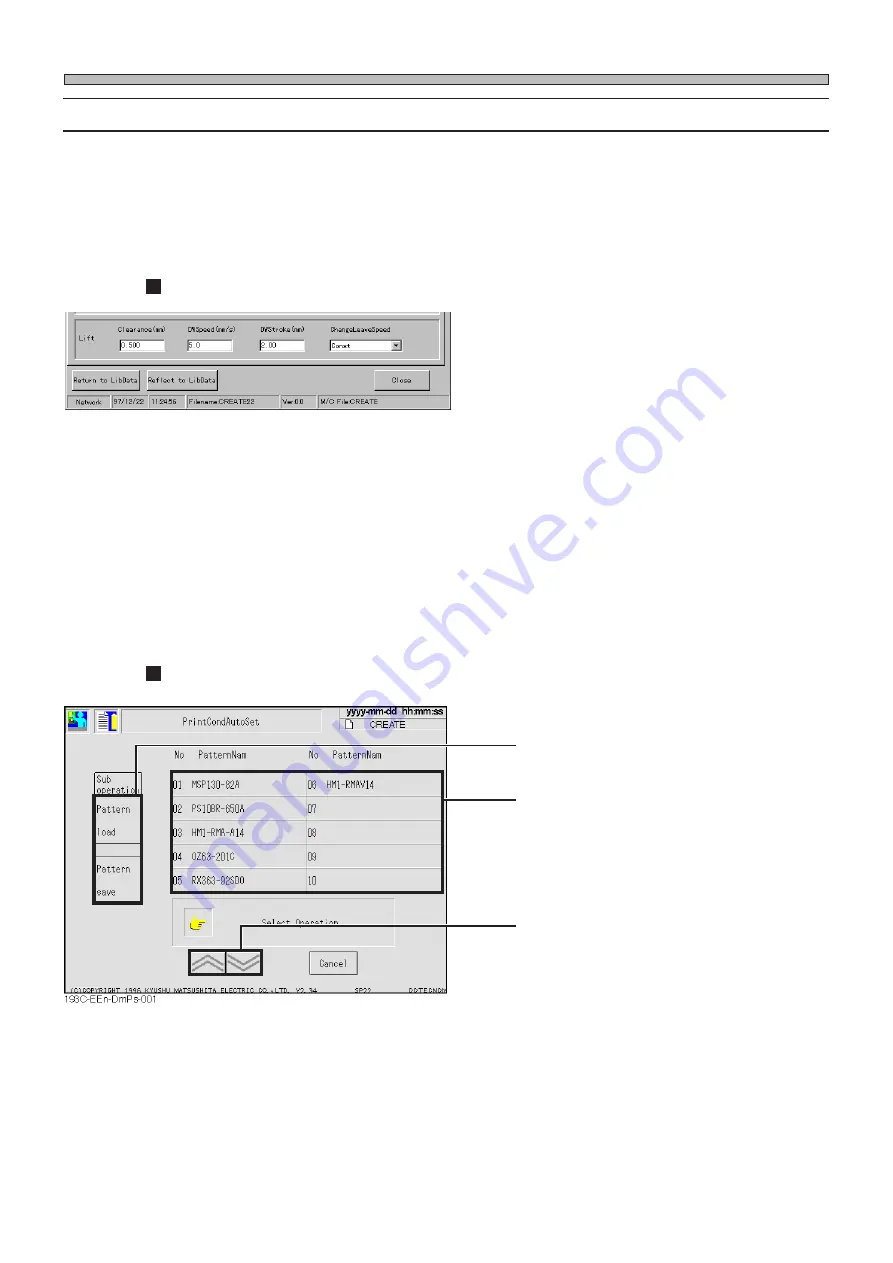
Choose load or save by pressing.

Pattern display field

Scroll the displayed patterns by pressing.

Summary of Contents for KXF-193C

Page 1: ...u for purchasing SP22P the screen printer Before placing the machine in service be sure to read the instruction manual for proper usage After that store it carefully and it if necessary 193C E EMAB 0002 Screen Printer SP22P Operating Manual Engineers ...

Page 2: ......

Page 3: ...01 00 M11E DO NOT ALLOW ANY PERSON WHO HAS NOT RECEIVED SPECIAL TRAINING TO OPERATE THE MACHINE The machine may be operated improperly and injure you Either carry out training by yourself or consult the manufacturer WARNING ...

Page 4: ...e precautions and information which is necessary for safe and effective operation Operating manual operators This manual This manual is for the machine engineers and describes operation method and teaching of boards and parts Operating manual engineers This manual is for machine maintenance and describes the daily checks adjustment and replacement of consumable parts Troubleshooting is also includ...

Page 5: ...neers Operating Manual Operating Manual 193C E EMA00 A02 20 SAFETY PRECAUTIONS OUTLINE OF EQUIPMENT BASIC OPERATION CHANGING THE PRODUCTION BOARDS DATA MODIFICATION TEACHING FILE OPERATION MACHINE ADJUSTMENT MACHINE SETTING APPENDIX ...

Page 6: ... 1 3 4 Outer Size 1 8 1 4 Other Specifications 1 9 1 4 1 Specifications of Board 1 9 1 5 Accessories and Spares 1 10 1 6 Main Option 1 11 Chapter2 BASIC OPERATION 2 1 Functions of Engineer Mode 2 2 2 1 1 Entering the Engineer Mode 2 2 2 1 2 Functions of the Main Menu 2 3 2 1 3 Menu Tree Functions 2 4 2 1 4 Changing Passwords 2 5 2 2 Functions during Production Stop 2 6 2 2 1 Maintenance 2 7 2 3 Da...

Page 7: ...ng Board Data 4 11 4 4 1 Board Data 4 11 4 4 2 Editing Board Data 4 12 4 5 Creating Board Recognition Data 4 13 4 5 1 Board Recognition Data 4 13 4 5 2 Editing Board Recognition Data 4 14 4 6 Board Positioning Data 4 15 4 6 1 Board Positioning Data 4 15 4 6 2 Editing Board Positioning Data 4 16 4 7 Mask Data 4 17 4 7 1 Mask Data 4 17 4 7 2 Editing Mask Data 4 21 4 8 Mask Solder Recognition Data 4 ...

Page 8: ...ognition Teaching 5 5 5 2 Board Recognition Teaching 5 6 5 2 1 Board Recognition 5 6 5 2 2 Flowchart of Board Recognition Teaching 5 6 5 2 3 Creating Procedures 5 7 5 2 4 Using the Block Match Recognition 5 10 5 3 Mask and Solder Recognition Teaching 5 11 5 3 1 Mask and Solder Recognition 5 11 5 3 2 Flowchart of Mask and Solder Recognition Teaching 5 11 5 3 3 Creating Procedures 5 12 5 4 Print Pos...

Page 9: ...Recognition 7 4 7 5 Printing 7 5 7 6 Mask Cleaning 7 6 7 7 Mask Recognition 7 7 7 8 Solder Supply Option 7 8 7 9 Test Printing 7 9 7 10 Squeegee Open and Close 7 10 7 11 Input Check 7 11 7 12 Output Check 7 12 7 13 Axis Information 7 13 7 14 Recognition Unit Maintenance 7 14 7 14 1 Updating the Recognition Device 7 15 Chapter8 MACHINE SETTING 8 1 Adjustment Switch 8 2 8 2 Time Setting 8 3 8 3 Reco...

Page 10: ...Page 10 193C E EMA00 A02 01 INDEX AppendixA RECOGNITION DEVICE ...

Page 11: ...gs are only some examples of the symbolic indications This indication refers to a situation which is considered that there is imminent danger of death or serious injury This indication refers to a situation which is considered that there is a possibility of death or serious injury This indication refers to a situation which is considered that there is a possibility of only injury or physical damag...

Page 12: ... have serious injury WARNING 193C E EMA00 A03 00 DANGER DON T TOUCH THIS PART WHEN OPERATING 0 8 6 R A 0 1 K 1 B DANGER DO NOT OPEN THE COVER WHEN OPERATING You will have serious injury if you touch the active part inside 0 8 F 1 A NO OPEN FLAME Solvent may catch fire Keep away from fire WARNING 0 1 N C B WARNING ELECTRIC SHOCK You will have serious electric shock if you touch electric active part...

Page 13: ... WHEN OPERATING You will have serious injury if you touch the active part inside 0 1 P 9 B WARNING DO NOT DISABLE SAFETY SENSOR You will have serious injury by active part if you disable safety sensor 0 8 F 1 A NO OPEN FLAME Solvent may catch fire Keep away from fire WARNING 0 7 R 3 A CAUTION IPA USE ONLY The corrosion damage to the hose may cause the machine to catch fire ...

Page 14: ...a breakdown or an accident will occur There are two emergency stop buttons Pressing any one of them stops operation Press the nearest one Remove the cause of the danger or abnormality then re start the machine To reset the emergency stop button pull it forward M33E 2B WARNING 193C E EMA00 A03 00 1 Front operation panel 2 Left pole on rear side 193C AA00 E MERGEN C Y STOP E MERGEN C Y STOP E MERGEN...

Page 15: ...ree levels of procedure shown below for each kind of work Cutting off the power supply of the machine For repairing the control box Power supply OFF This is used to turn off power supply normally For replacing the control part such as the sensor For disassembling or replacing parts Servo switch OFF For changing production board and daily inspection For placing or removing board on the conveyor For...

Page 16: ...Page 16 SAFETY PRECAUTIONS Be sure to observe DANGER L06EB DO NOT OPEN THE COVER WHEN OPER ATING You will have serious injury if you touch the active part inside 193C E EMA00 A03 00 ...

Page 17: ...INCH YOUR HANDS OR FINGERS You will have serious injury if your hands or fingers are caught in the conveyors during manual or automatic width adjustment M02E BEFORE INSPECTING PNEUMATIC EQUIPMENTS CUT OFF THE AIR SUPPLY AND EXHAUST AIR FROM THE EQUIPMENTS You will have serious injury if the residual pressure actuates the machine Before inspecting pneumatic equipment cut off the air supply and exha...

Page 18: ...hine repaired or adjusted by a trained professional maintenance engineer Consult the manufacturer for training DO NOT PLACE YOUR HANDS OR BODY INSIDE ACTIVE PART OF THE MACHINE WHEN IT IS IN A SINGLE STOP OR CYCLE STOP CONDITION The machine has been stopped only temporarily You may be injured if the sensors are actuated and the machine moves unexpectedly Turn OFF the servo switch before placing yo...

Page 19: ...9EB M06E GROUND THE MA CHINE PROPERLY There is a risk of an electric shock or leak Consult a professional electrical contractor PERIODICALLY REMOVE DUST FROM POWER PLUG Dust on the plug may result in fire caused by defective insulation because of moisture Pull out the power plug and wipe off dirt with dry cloth If the machine is not going to be used for a long period turn off the breaker connected...

Page 20: ...d inlet M23E ONLY THE PERSON IN CHARGE MUST CHANGE THE DATA The machine may runaway or malfunction The data must be changed only by a trained specialist in charge IPA ISOPROPYL AL COHOL USE ONLY The corrosion damage to the hose may cause the machine to catch fire L28EB BE CAREFUL OF THE MOTOR You may strike your head on the protruding motor and be injured M22EB M26EB BE CAREFUL OF THE PNEUMATIC PR...

Page 21: ...e machine cannot exhibit its true performance Also it may break down or produce defectives Periodic inspection and maintenance should be carried out by a trained person in charge of maintenance according to the instructions in MAINTENANCE MANUAL BEFORE PERFORMING AUTOMATIC WIDTH ADJUSTMENT BE SURE TO VERIFY NO BOARDS OR OTHER OBJECTS ARE ON THE CONVEYOR Boards or other objects may drop from the co...

Page 22: ...CAUTIONS Be sure to observe 193C E EMA00 A03 00 CAUTION BE CAREFUL IN HAN DLING IPA ISOPRO PYL ALCOHOL Isopropyl alcohol is harmful to the human body Wear the mask to avoid organic odor when using isopropyl alcohol M84EB ...

Page 23: ...ch for maintenance at our company This switch which is targeted for the technician belonging to our company or the commis sioned maintenance technician can release all of the safety cover interlocks It is used for such an extensive maintenance work as you cannot perform 2 Feature of key switch for maintenance at our company It is dangerous to use this maintenance key because the safety cover inter...

Page 24: ...g in the cleaning solvent leakage Never use methanol methyl alcohol The use of methanol breaks the solvent pump and disables its function Cleaning solvent may catch fire Handle with great care Use unused cleaning solvent Do not use water or the mixture of water and other cleaning solvent as the cleaning solvent Rust or change in quality of cleaning solvent may choke piping and damage the machine W...

Page 25: ...35mm 5mm width of cleaning solvent onto the cleaning paper for the wet cleaning Adjustment method Adjust the discharge amount with the regulator on the back of the machine next to the cleaning solvent container The increase of pressure makes the dis charge amount larger The decrease of pressure makes the dis charge amount smaller 0 147 MPa to 0 196 MPa 35 mm 5 mm d e e p S s m m n r e t t a P m u ...

Page 26: ...ntains a small amount of mercury It also contains lead in some components Disposal of these materials may be regulated in your community due to environmental considerations For disposal or recycling information please contact your local authorities or the Electronics Industries Alliance 193C E EMA00 A04 00 ...

Page 27: ... attached to the machine Operate and maintain the machine according to the instructions on the label 1 Nameplates on X Y table are for maintaining machine s accuracy 193C AE00 0799C2AA X Y table Two plates are attached to the Y axis cover 1 193C E EMA00 A04 00 ATTENTION DON T PUT YOUR HANDS ON THIS COVER ...

Page 28: ...per handling Make sure to back up the program and data on a disk to protect against the loss of data To back up the program and data make another copy disk of the same contents See the disk copy in the section of file operation for how to back up 2 Write Protection The stored data may be mechanically protected from accidental erasure or rewriting Write protection may be set or disabled by sliding ...

Page 29: ...e put in the case pro vided for storage or transportation A disk should not be stored or left in areas exposed to the following conditions Do not apply excessive force to the disk Do not place heavy objects on the disk Automatic shutter The automatic shutter should not be opened Do not touch the magnetic circu lar disk inside Refrain from smoking drinking and eating close to the disk Any loose lab...

Page 30: ...ge 30 SERIAL PLATE The serial plate attached to this machine indicates the model name and production number 193C AB00 Actual numbers are shown on the plate instead of 193C E EMA00 A04 03 SP22P M KXF 193C ...

Page 31: ...4 00 Title Title Actual operation Actual operation Supplementary description on operation Supplementary description on operation Operating procedure number Operating procedure number These show operation flow These show operation cause and its effect This shows the item to refer This shows operation by engineers This shows pressing a key on touch panel This means pressing UNLOCK and then START on ...

Page 32: ...Page 32 193C E EMA00 A04 01 MEMO ...

Page 33: ...ine change The new type of cleaning unit and digital head with feedback function enables the high quality printing under the best condition Also the low pressure printing using the super hard squeegee controls scoop or blur and our original plate parting control enables the stable fine pitch printing Besides the data creation by off line system makes it easy to see the display and to operate SP22P...

Page 34: ...he board stopper or holder etc 1 1 2 High Quality Printing The new type of digital head with feedback function is set The set print is properly achieved by not only the digital setting of printing pressure but also detecting the opposite force by the mask during printing and running the feedback The full floating print at the low print pressure and our original plate parting control carry out the ...

Page 35: ...der supply unit optional is the easy type to set directly to the head and it does not need any maintenance Using it with cleaning unit together enables automatic operation for a long time 193C E EMA01 A01 00 Characteristics of Machine Screen mask Mask Operator Wit nozzle Vacuum unit Mask cleaning unit Moving direction 193C 048E Solder paste Cleaning unit Sensor with dirt detecting sensor Squeegee ...

Page 36: ... our standard library Besides 14 patterns can be added as for the user s creation PT100 support models High speed screen printer SP22P M High speed adhesive dispenser BD30S M High speed chip mounter CM88C M Multi functional chip mounter CM100 M The system for data creation PT100 193C 051E 193C E EMA01 A01 00 Characteristics of Machine 193C 052E PrintCondition File F Help H AA Read from Library Pat...

Page 37: ...rinciple Mechanism of Printing This printer with the front and rear squeegees piles masks on the board and fill up the solder paste to the mask opening then duplicates the solder on the board 193C E EMA01 A01 00 Solder paste 1 Mask 2 Squeegee Board ...

Page 38: ...i r p t o n y a m t n e m e v o m e e g e e u q S e l b a e g n a h c e r a s e e g e e u q s e l b u o d d n a e l g n i S n o i t c e r r o c g n i n o i t i s o p d r a o B 5 1 f o n o i t c e r i d g n i t a t o r s n o i t c e r i d Y d n a X o t m m 5 y c a r u c c a g n i t n i r P n o i t i d n o c t n i r p d e d n e m m o c e r e h t r e d n u m m 3 0 0 y r o m e m r e t u O a t a d f o ...

Page 39: ...AAA AAAAAAAAAAAAAA AAAAAAAAAAAAAA AAAAAAAAAAAAAAA AAAAAAAAAAAAAAA AAAAAAAAAAAAAAA AAAAAAAAAAAAAAA 193C 054E Operator Automatic width adjustment Board flow direction Fixed side Y X Fixed side 193C 053E Space for transferring 5 24 10 5 15 5 Z Y Board Specifications of Device 193C E EMA01 A01 00 Reference ...

Page 40: ... EMA01 A01 00 Specifications of Device 1 3 4 Outer Size Adjustment bolt X Y table Board transfer height 900 1600 2000 25 250 675 675 25 250 1400 1900 1600 99 775 Board flow direction Fixed side 193C 055E 193C 056E 70 ...

Page 41: ...ard recognition mark Examples of mark The board recognition is corrected by the positional relation between the recognition mark and the circuit pattern The fixed contrast is required for the recognition mark and board binary contrast image Mark size and background Non interference area larger than the fixed size which is different from that mark is required for the background of mark Non interfer...

Page 42: ... p 4 k s i d y p p o l F m e t s y s r o F e c e i p A n o i t a l l a t s n i m e t s y s r o F e c e i p A m e t s y s n e e r c S s e c e i p 2 n o i t a l l a t s n i n e e r c s r o F e c e i p A m e t s y s n o i t i n g o c e r r o F e c e i p A U R P e n i h c a m a t a d r o F e c e i p A r e t e m a r a p e n i h c a m a t a d r o F e c e i p A s d r o w s s a p g n i g n a h c r o F e c...

Page 43: ... H 0 5 C A W 0 6 2 2 e m u l o v g n i t a e h c i r t c e l E W k 4 2 l l e m s r o t s u d r o f s n o i t u l o S r e t l i f n o d e l l i F t n e m p i u q e n i e r u t a r e p m e t l o r t n o C 0 2 0 3 C C 0 2 e r u t a r e p m e t g n i d n u o r r u S 0 3 C C e m u l o v k n a t n i a r D 0 2 l e c i v e d g n i t c e t o r P r e v o r o t a l i t n e v r o t c e t o r p r o t o m r o s...

Page 44: ...hed Pickup block Board holder unit Flat squeegee holder for narrow pitch Dagger squeegee holder Square squeegee holder L 270 220 170 mm others For ceramic board Squeegee parallel adjustment Set the shutter for board recognition camera Fix the squeegee to keep parallel to the mask L 350 270 170 mm others L 350 mm ...

Page 45: ...QUIPMENT 193C E EMA01 A01 00 Main Option 2 2 Items Appearance Temporal type of automatic solder paste supply unit Mask cleaning unit for small frame 193C 066E Squeegee Squeegee head setting board Digital head Syringe 193C 067E ...

Page 46: ...Page 1 14 193C E EMA01 A01 01 MEMO ...

Page 47: ... of touch panel are divided into the operator and engineer modes up to its purpose to prevent wrong operation This section describes the main menu for the engineer mode See the manual for operators for the menu and operation switches under the screen for the operator mode Main menu of engineer mode ...

Page 48: ... Mode The password is required to enter the engineer mode If the password is not set see 2 1 4 Changing Passwords and set it 1 Press Engineer The password input screen appears 2 Enter the password and press Decision The main menu of engineer mode appears If wrong numeral is entered press the BS key and reenter ...

Page 49: ... e c n a m r o f r e P o f n i t e s e r d n a d e y a l p s i d s i n o i t a m r o f n i n o i t c u d o r p e h T r e e n i g n E y f i d o m a t a D t h g u a t d n a d e t c e r r o c s i a t a d n o i t c u d o r P e l i F t n e m e g a n a m y b d e d a o l d n a d e v a s e r a r e t e m a r a p e n i h c a m d n a a t a d n o i t c u d o r P k s i d y p p o l f d n a 0 0 1 T P e n i h c a...

Page 50: ...u tree appears on any screens by pressing the key Pressing the icon switch on the menu tree opens that operating menu 193C E EMA02 A01 01 193C EEn PrIs 001 193C EEn MaAi 001 193C EEn Mp 001 Press the key under the screen Press the icon The operation menu of pressed icon appears See the previous page for contents Pressing Main menu displays the main menu for the engineer mode ...

Page 51: ...change 4 Enter the new password and press Decision 5 Enter the new password again and press Decision If the password entered at the procedure 4 matches to that at 5 the password is changed and the main menu for the operator mode reappears 6 Press Engineer and check if you can enter the engineer mode or not If it is not carried out properly repeat opera tions from the procedure 3 7 Take out the key...

Page 52: ...unts are indicated and reset The machine state independent of the produc tion data is set See Chapter 8 Machine Setting for details The machine data is corrected See Chapter 4 Data Modification for details M34EB WARNING DO NOT PLACE YOUR HANDS OR BODY INSIDE ACTIVE PART OF THE MA CHINE WHEN IT IS IN A SINGLE STOP OR CYCLE STOP CONDITION The machine has been stopped only temporarily You may be inju...

Page 53: ...ctive only for the cycle stop Cleaning 2 round 2 round mask cleaning is carried out It is effective only for the cycle stop Sent out air of solvent The air in the pipe is discharged by running the pump Escape XY table The XY table is retracted to the inner side It is used to clean the reverse side of mask by hand Recog unit maint The recognition device maintenance screen appears See 7 14 Recogniti...

Page 54: ... the numeral window 3 Press ENT The set item changes to the entered numeral and the cursor moves to the next item b Directly setting 1 Directly press data to correct with fingers It is highlighted 2 Enter numerals with numerical keys If wrong numeral is entered press BS to reenter The entered numerals are displayed at the window 3 Press ENT The specified item changes to the entered numeral and the...

Page 55: ...evice for the board and supply production materials This section describes the changing operation of production boards taking data of production board on PT100 Machine adjustment points with the change of production boards Board holder unit 193C AD00 18A4C0AA Squeegee head 15V6C0AA Left conveyor 11DJC2AA Right conveyor 11DKC2AA Board positioning and lift 18A5C2AA Cleaning head 1939C2AA 1937C2AA Sc...

Page 56: ...tion are available To load data of the floppy disk see Chapter 6 File Operation Loading data to use deletes data used by now To store data used by now save it a Transfer from PT100 to this machine 1 Display the main menu screen and send data of the production board to change from PT100 See PROGRAMMING MANUAL for sending data from PT100 Sending data from PT100 changes the data name on the right of ...

Page 57: ...ration 1 Press File managment The file operation screen appears 2 Press PT100 Change the device object to PT100 To display data of PT100 by this machine it is necessary to register in the list on PT100 PROGRAMMING MANUAL 3 Press Load Load is highlighted To the next page 193C E EMA03 A01 00 ...

Page 58: ...ame to load The selected data name is highlighted 6 Press Yes Loading data starts To quit loading data press No The message Loading data appears When loading ends the data name on the right of screen changes to the loaded data name 193C E EMA03 A01 00 1 2 ...

Page 59: ...detected The board positioning and lift and rail width adjustment are carried out according to new board data M36E If there are any boards or other objects on the conveyor turn OFF the servo switch and remove them BEFORE PERFORMING AUTOMATIC WIDTH ADJUSTMENT BE SURE TO VERIFY NO BOARDS OR OTHER OBJECTS ARE ON THE CONVEYOR Boards or other objects may drop from the conveyor causing damage to the boa...

Page 60: ...e the board under holder block The block plate is fixed with a magnet or bolts As for the block fixed with a magnet remove the block pulling it up As for the block fixed with bolts take out bolts at fast to remove the block Also remove it in using the matrix plate or the board pickup box and plate alike 3 Remove the board under holder plate on the movable side Remove two of M3 bolts under the plat...

Page 61: ...f front and rear transfer conveyors and board holder are automatically adjusted 1 Turn on the servo switch 2 Press Machine adjust The machine adjustment menu screen ap pears 3 Press UNLOCK Return to origin Each station starts to return to their origin If the power is turned off turn on the power after that operation is displayed To the next page OFF ON SERVO ...

Page 62: ...nt screen appears 5 Press UNLOCK and Run The width is adjusted for the set board Conveyor width adjust preparing The message Conveyor width adjusting appears and the transfer rail is automatically adjusted 6 Press The machine adjustment menu screen reap pears 7 Press The main menu screen reappears 193C EEn MaWa 001 193C EEn Ma 001 ...

Page 63: ...e procedure 3 2 1 1 Turn off the servo switch 2 Set the board under holder plate on the movable side to the conveyor on that side Fix the lower part of plate with two of M3 bolts Set the under holder plate so that the gap between it and the clamp plate on the movable side gets 1 mm to 2 mm Set it not to shield the under holder interlock sensor attached to the conveyor on the mov able side OFF ON S...

Page 64: ...se a Board under holder pin optional The board is supported by pins Use this for boards for dual side mounting b Board block The board is supported by the plate block Use this for boards for the single side mounting c Board pickup box and plate optional The board is supported by the vacuum pickup Use this for pin positioning or such boards as ceramic and thin card type a Setting the board support ...

Page 65: ...sary board under holder blocks for each board size The width of a board under holder block is 40 mm As for the nearest block to the conveyor on the fixed side set the block only for that side c Setting the board pickup box and plate optional 1 Set the board pickup box and plate only for that machine type Connect several pipes coming out of the box to the joint in the inner side 193C E EMA03 A01 00...

Page 66: ...ality of board 1 Turn the regulator knob for the board clamp to adjust Pull up the knob upward and turn it After adjustment push it down The relation between the value of air pressure and the board clamp force is as follows Regulator knob for board clamp Air pressure 0 098 MPa 0 196 MPa 0 294 MPa 0 392 MPa Board clamp force 15 4 N 30 8 N 46 2 N 61 5 N ...

Page 67: ...oard holder bars according to the board size 2 Press Data modify The data modification screen appears 3 Press PCB positioning data The board positioning data screen appears 4 Turn on the board holder to move 5 Press The main menu screen reappears 193C E EMA03 A01 01 Bar Loosen this screw and adjust the interval between board holder bars 193C EEn Dm 001 193C EEn DmBr 002 193C 076E 18A4C0AB ...

Page 68: ...data in following procedures 1 Press Data modify The data modification menu screen appears 2 Press Form print The form print screen appears 3 Press Print cond data 4 Press Run The form is output through the printer Repeat the same procedures for the cleaning data and print counter to print To quit the form print press STOP on the operation panel 4 13 Form Printing To the next page 1 2 ...

Page 69: ...ss The main menu screen reappears 193C E EMA03 A02 01 193C EEn Dm 001 193C EEn MaFp 001 YYYY MM DD HH MM SS Data CREATE Print cond data F mm s 50 Offset F 0 000 Clearance 0 000 Down speed 0 8 Down stroke 1 50 Speed change Const Offset R 0 000 R mm s 50 WaitPrnt 0 00 Pressure F 10 000 Pressure R 18 000 Length 350 000 Squeegee Act mode Single Priority Lifter Kind Flat Squeegee Angl deg 60 Print rang...

Page 70: ... on the screen during board transferring NOTICE Actually the transfer test for whole line is carried out This section describes the board on the rear conveyor in the pre station after the transfer test before the pre station 1 Turn ON the servo switch 2 Press Product config The production setting screen appears 3 Press PCB transfer The board transfer screen appears 193C E EMA03 A02 00 To the next ...

Page 71: ...ositioning is carried out 6 Press UNLOCK and Unload The board is transferred from the middle conveyor to the rear conveyor 7 Press UNLOCK and Carry out The board is transferred from the rear conveyor to the post station Repeating the same operation makes a board transfer error Press the emergency button and remove the board 8 Press The production setting screen reappears 9 Press The main menu scre...

Page 72: ...on data 1 Turn on the servo switch 2 Press Machine adjust The machine adjustment screen appears 3 Press Squeegee open close The squeegee open and close screen appears 4 Press UNLOCK and SQ open Squeegee change Select the origin side 193C E EMA03 A02 00 OFF ON SERVO To the next page ...

Page 73: ...nd re move the squeegee Remove both of F and R squeegees 7 Fit the print mark for positioning to the left and right to the edge of holder to set and tighten the knob 1 Set the F and R squeegees To the next page Fit edges to the print mark OFF ON SERVO F squeegee Knob 1 R squeegee Knob 2 Holder 193C 069E Squeegee holder 193C 027P 193C 028P ...

Page 74: ...Q close The squeegee closes 10 Loosen the T type knob 2 and turn the knob 3 looking at the angle dis played on the screen to adjust the angle slightly 193C E EMA03 A02 00 The angle is displayed by the angle adjustment OFF ON SERVO To the next page T type knob 2 Knob 3 193C 029P ...

Page 75: ... knob 2 12 Press The machine adjustment menu screen reap pears 13 Press The main menu screen reappears T type knob 2 193C EEn MaSoc 001 193C EEn Ma 001 193C 030P Changing Squeegees 11 After adjusting the angle tighten the T type knob 2 12 Press The machine adjustment menu screen reap pears 13 Press The main menu screen reappears ...

Page 76: ... the Mask The mask for the board to print is set 1 Turn OFF the servo switch 2 Set the mask Check the board pattern not to set the inner and front masks improperly 3 Turn ON the servo switch To the next page OFF ON SERVO OFF ON SERVO 193C 031P ...

Page 77: ...Press Data modify The data modification screen appears 5 Press Prod data teach The production data teaching screen appears 6 Press Mask Paste recog Carry out mask solder recognition teaching See 5 3 Mask Solder Recognition Teaching for details 193C E EMA03 A02 01 ...

Page 78: ...print pressure teaching after changing squeegees 1 Press Pressure The print pressure teaching starts The switch lights during teaching As the setting value of squeegee print pressure does not affect the print pressure teaching you can set any value for the print pressure After teaching pressing returns to the data modification screen 2 Press The main menu screen reappears 193C EEn DmPdt 001 193C E...

Page 79: ...t The printing state is checked by printing test 1 Press Machine adjust The machine adjustment menu screen ap pears 2 Press Test print The test printing mode screen appears 3 Press Print state check The printing check screen appears See 7 9 Test Printing for details 193C E EMA03 A02 01 ...

Page 80: ...Page 3 26 193C E EMA03 A02 01 MEMO ...

Page 81: ...w to edit and create production data Production data can be edited on PT100 and this machine only some data can be modified through the data modifying function For the PT less specification all data can be edited on the machine Chapter 4 DATA MODIFICATION DATA MODIFICATION ...

Page 82: ... operations and screens which are greatly different from those of the PT When using the PT less specification read the instructions and adapt as follows PT100 screen Board data SP22 screen Board data PT100 operation SP22 operation 1 Click on Press 2 Click on Close Press Click the close button 3 Pull down menu Every pressing a button toggles the display Together Lifter Squeegee 193C E EMA04 A01 02 ...

Page 83: ... specification PT specification PT Filer Create production data Start Editor to edit the created data Download the edited production data including each recognition data PT SP22 Editor Start it from Filer Edit the production data of SP22 Input each detailed data including each recognition data Set function switches including whether or not to recognize SP22 You can modify some production data incl...

Page 84: ... production quality 1 Outline of board data Board data Recognition data Positioning data Input the data of the board to be printed 2 Mask Data Input the size of the mask and the plate making reference X Y T 3 Batch teaching data This data is necessary for positioning the mask and the board by using the board recognition mark 3 Mask recognition data Input the data necessary for positioning the mask...

Page 85: ...g the printing condi tions data by using the library When modifying a part of the printing conditions data 5 Printing conditions data Library Load the data from the library 5 Printing conditions data Set the squeegee motion and the lift motion 6 Cleaning data Set the method of mask cleaning 7 Printing counter Set the solder dispense data 8 Solder recognition data Set the recognition counter and th...

Page 86: ...n starting a new data file see 4 2 2 Starting New Data File 4 2 2 Starting New Data File When you start the Editor of a data file created newly by the Filer the following screen is displayed The data chosen from the registered library data are copied to 4 9 Printing Conditions Data 4 9 3 Cleaning Data and 4 9 5 Printing Counter 1 2 193C E EMA04 A01 03 ...

Page 87: ...ry data and the chosen library data name is displayed in the Refer ence field 21 pattern library data have been prepared as the standard data 2 Previous Next The previous or next pattern is displayed by clicking Delete This is used to delete the printing conditions data saved in the library When the printing conditions data is saved in the library this switch is displayed 193C E EMA04 A01 02 3 ...

Page 88: ...it its command menu opens Then drag the mouse to choose the command Some menus contain sub menus Buttons for each type of data editing When you click on a button the screen for that data editing is displayed Buttons for each type of function When you click on a button its function function setting screen is displayed 1 Menu bar 2 Buttons for each type of data editing 3 Buttons for each type of fun...

Page 89: ...lays the help screen Sub menu 193C E EMA04 A01 04 Displays the chosen data editing screen Used to print each data Closes each data editing screen or finishes the data editing 4 2 5 Exiting Editor When you click on Close on the main menu the following screen is displayed To exit Editor choose the saving method then click on OK ...

Page 90: ...g Data SP22 This section describes the initial step necessary for editing and modifying data on this machine 1 Press Data modify on the main menu Data modify menu is displayed Pressing any button displays that data s setting screen Pressing displays the main menu ...

Page 91: ...rdinates etc 3 Origin offset Enter the offset value Origin offset is used to set the origin 0 0 onto a position that is offset from the board corner as the coordinates reference Offset value is the measurement from the board corner selected as the coordinates reference to the origin 4 Stop position This can be set only on SP22 This displays the position on X Y table where the board will be clamped...

Page 92: ...e example that follows 1 Click on BoardData on the main menu BoardData sheet on BoardData window opens 2 Enter the size of the board Enter the board size L W and T 3 Choose a coordinates reference Enter origin offset if necessary 4 Click on Close The main menu is displayed 193C E EMA04 A02 00 ...

Page 93: ... Y Enter the measurement X Y from the origin to the board recognition mark E g Right Rear reference Coordinates of board recognition point A X1 Y1 Coordinates of board recognition point B X2 Y2 Choose the two marks on board as the recog nition A and B points The two points must be located diagonally and as distant from each other as possible b REF Choose the method of recognition Shape recognition...

Page 94: ...Enter the coordinates of board recog nition point A 3 Click on SelectREF SetREF window opens 4 Choose the REF shape and color enter the size and then click on OK SetREF window closes and BoardRecogData sheet opens 5 Input the data of point B by repeating the steps from 2 to 4 When you have selected points AB Pa and AB PaPb input the data of the points Pa and Pb in the same way 6 Click on Close The...

Page 95: ... material is such as ceramic and iron Lower limit After the board is clamped at its lower limit and then the set delay time has passed the support block begins to rise up This is effective for the boards whose material is such as glass epoxy and paper phenol 2 Board stopper motion Set the use of the board stopper at the time of positioning and the Y direction position of the stopper at the time of...

Page 96: ...the board the solder might spread due to such things as the through hole when the board is vacuumed In such a case Set OFF the vacuum during printing Vacuum during printing Set whether to use the board vacuum function during printing For the vacuum start time input about 0 3 s as the delay time of board clamp motion When Inputting the vacuum end time consider the lowering speed and lowering stroke...

Page 97: ...sk Data 4 7 1 Mask Data 1 Mask registration No When registering mask data input the registration No and a name that describes it 2 Mask size Enter the size of mask Y length X width and T thickness Operator s side X Y T 193C E EMA04 A02 00 ...

Page 98: ... of Y direction mask frame 250mm 330mm 550mm 160mm 250mm 200mm 150mm 650mm 250mm 330mm 550mm CL 250mm 650mm 160mm CL Sample board pattern position Transport direction 650X550 mask X direction center distribution Position of 150mm from the inner side of Y direction mask frame 550X650 mask X direction center distribution Y direction center distribution 650X550 mask X direction center distribution Y ...

Page 99: ... mask Position of 160mm from the right edge side of X direction mask frame Y direction center distribution Left Center 550X650 mask Position of 110mm from the left edge side of X direction mask frame Y direction center distribution 650X550 mask Position of 110mm from the left edge side of X direction mask frame Y direction center distribution 330mm 550mm 250mm 650mm 160mm CL 250mm 110mm 160mm Samp...

Page 100: ...irections The example mask on the left 550 X 650 is made as longitudinal frame standard and rear center reference Therefore when you choose the plate making reference as rear center the left position is the origin of the mask of this machine Sample board pattern position 250mm 330mm 550mm 160mm 250mm 200mm 650mm X Y Positive and negative direction of the difference 193C E EMA04 A02 00 ...

Page 101: ...k Data 1 Click on MaskData MaskData window opens 2 Enter the mask registration No and name 3 Enter the size of the mask 4 Choose a plate making reference 5 Enter the Plate making reference origin 6 Click on Close The main menu is displayed 193C E EMA04 A02 00 ...

Page 102: ...f the solder recognition solder printed area inspection and clogged mask inspec tion It is not possible to input 0 time So if you do not use the solder recognition function turn OFF the print status recognition in the function switches 2 Recognition mode Choose a solder recognition mode 2 block mode 1 to 4 points are recognized 5 block mode 1 to 10 points are recognized Usually choose the 2 block ...

Page 103: ...osition correction Solder is recognized When you perform the printing condition check of machine adjustment the deviation quantity of solder is calculated and the offset data of the printing position check position is corrected c 1point 1pair Choose 1 point recognition or 1 pair recognition for each block Unless the precision is especially important set 1 point recognition d 1point 1pairX 1point 1...

Page 104: ...n Mask Paste Recog Mask Paste Recog window opens 2 Set the solder recognition counter When regarding the check as important Set the higher number of times When regarding the tact time as important Set the lower number of times 3 Choose a recognition mode To the next page 193C E EMA04 A02 01 ...

Page 105: ...cognition function 6 Choose 1 point or 1 pair 7 Input the coordinates of the recogni tion point 8 Input the next block data by repeating the steps from 5 to 7 9 Click on DataShift Board Mask The coordinates of the board side are copied to those of the mask side 10 Click on Close Main menu is displayed again 193C E EMA04 A02 00 ...

Page 106: ... The squeegee is fixed and the mask is released while the squeegee is down After that the squeegee rises up Squeegee After the squeegee has been raised the mask is released Together Raising the squeegee and releasing the mask start simultaneously When this mode is set the mask release speed changeover is fixed to the uniform velocity mode c Printing Speed d Printing Pressure e Length f type g Angl...

Page 107: ...Choose the descending speed from among the following three modes Uniform velocity mode The support block lowers the descending stroke distance at a uniform velocity Acceleration mode The speed of support block accelerates slowly and eventually it reaches the descending speed Multiple mode The speed of support block accelerates slowly and eventually it reaches the descending speed When the mask rel...

Page 108: ... Editing Printing Conditions Data 1 Click on PrintCondition on the main menu PrintCondition sheet on PrintCondition window opens 2 Set the data about the squeegee 3 Set the printing range 4 Set the data about the lift 5 Click on Close The main menu is displayed ...

Page 109: ...g time such as while waiting for the next process etc 5 Waiting time Input the waiting time until the cleaning during wait of process starts 6 Speed Set the speed of the cleaning motion 7 Method Choose a cleaning method from either the wet or dry process Choose the wet process only in order to remove the flux of solder on the mask The wet process is not available for the backward cleaning motion 8...

Page 110: ...ormance may be insufficient depending on the type of solder Recommended conditions for mask cleaning Cleaning tact time For the case where board size is 460 X 360 1 round About 26 s 2 round About 50 s If the cleaning performance is not good using the conditions on the left reduce the cleaning speed more Forward Backward Forward Backward Dry Dry Wet Dry 1 2 Removes solder balls and flux Removes the...

Page 111: ...ingData CleaningData sheet opens 2 Choose the motion mode 3 Set whether to perform the cleaning during a wait of process and the amount of waiting time 4 Set the speed and method of clean ing and whether to perform the suc tion function 5 Click on Close The main menu is displayed 193C E EMA04 A03 00 ...

Page 112: ...is dis pensed When no solder is detected by the remaining solder check during F R printing solder is dispensed automatically set in the function switch When the solder autodispensing is OFF Sensor is disabled The paste count decreases one by one when ever one board is printed during an automatic operation When it is 0 the automatic opera tion stops or solder is dispensed automatically set in the f...

Page 113: ...ditions Data 4 9 6 Editing Printing Counter 1 Click on PrintCounter PrintCounter sheet opens 2 Set the paste count 3 Set the method of solder runout check and the dispensing time 4 Click on Close The main menu is displayed 193C E EMA04 A03 00 ...

Page 114: ... as a set 6 patterns for each type of solder have been prepared for the standard library data Moreover it is possible to add the library data user creates Case of PT specification 1 Return to LibData Read from Library window opens and the data are loaded from the registered library data 2 Reflect to LibData The edited data are saved as library data Case of PT less specification 193C E EMA04 A03 00...

Page 115: ...onditions Data to Library Data Case of PT specification 1 Click on Return to LibData Read from Library window opens 2 Choose the name of the pattern li brary to load 3 Click on OK Make sure the loaded data name appears in the PatternLibrary and Reference fields 193C E EMA04 A03 00 ...

Page 116: ... of PT less specification 1 Press PrintCondAutoSet in Data modify menu PrintCondAutoSet screen is displayed 2 Press 3 Choose the name of the pattern to load The pattern begins loading After it has been loaded pressing displays Data modify menu Pattern load 1 2 ...

Page 117: ...4 9 9 Reflecting Printing Conditions Data on Library Data Case of PT specification 1 Click on Reflect to LibData Write to Library window opens 2 Input the pattern library name 3 Click on OK The data are registered in the pattern library 193C E EMA04 A03 00 ...

Page 118: ...ndAutoSet screen is displayed 2 Press 3 Press a pattern No where nothing is currently saved The key operation screen for entering a pattern name is displayed 4 Enter the pattern name and then press ENT The pattern begins saving After it has been saved pressing displays Data modify menu 193C E EMA04 A03 00 Pattern save ...

Page 119: ...n data may change 2 Printing position offset This is used when the positioning deviation occurs due to the difference of squeegee printing direction or when the subtle deviation occurs due to the expansion of the mask etc even after the mask recognition Normally set it to 0 And when the position correcting flag of solder recognition data is ON the deviation detected by the printing conditions chec...

Page 120: ...dow opens 2A Confirm the correct result When all the data are correct data editing is completed Click on Close to return to the main menu or 2B Confirm the incorrect result If there are any errors in the data click on Close modify the data displayed as incorrect and then perform the data check again 193C EPt Ed 001 193C EPt EdDc 001 193C EPt EdDc 002 193C E EMA04 A03 01 ...

Page 121: ...c s i k s a m e h T n o i t i n g o c e r e t a t s g n i t n i r P r e d l o s d e t n i r p e h t g n i z i n g o c e r y b d e k c e h c s i g n i t n i r p f o e t a t s e h T n o i t i n g o c e r r e d l o s r e t f a g n i n a e l C n a g n i r u d n o i t i n g o c e r r e d l o s e h t y b d e t c e t e d s i d r a o b d e t n i r p n u a n e h W d e l l o r t n o c s i n o i t o m g n i ...

Page 122: ...nction Switch 1 Click on FuncSwitch FuncSwitch window opens 2 Set ON the function to be executed on the machine side during produc tion After setting click on Close to return to the main menu 193C EPt Ed 001 193C EPt EdSs 001 193C E EMA04 A03 01 ...

Page 123: ...Form Printing This is used to print out the data of chosen item s 1 Preview PT only See the next page 2 Form Printing After setting for printing the data are printed out to the printer On SP22 data are printed out to the built in printer 193C E EMA04 A03 00 ...

Page 124: ... the pages to be printed out is displayed 2 Previous Next The previous or next page from the current page is displayed 3 Reduce Magnify The current page zooms in or out 4 Print After setting for printing data are printed out to the printer 5 Set Font It is used to set the font style and size 6 Set Form It is used to set the form size paper supplying method printing direction margin and printer 193...

Page 125: ...off the item s you will print out is displayed at the head of the selected item 3 Click on Print Performs printing following the settings for printing When checking or editing the printing image click on Preview 4 Click on Close The main menu is displayed 193C EPt Ed 001 193C EPt EdFp 001 193C EPt EdFp 001 193C E EMA04 A03 01 ...

Page 126: ...r recognition data will be the data for mask recognition and solder recognition 2 Recognition position Set the mask recognition coordinates and the mask recognition mark shape for batch teaching a Copy BoardRecogData When it is clicked on the coordinates of the board recognition points are copied to those of mask recognition points 3 Data modification Decide whether or not to reflect the result of...

Page 127: ...a 4 14 2 Editing Batch Teaching Data 1 Set the batch teaching function to Use 2 Input recognition position data 3 Click on Copy BoardRecogData Mask recognition data is written to board recognition data 4 Set the data modification to Yes 193C EPt Bt 001 193C EPt Bt 001 ...

Page 128: ...Page 4 48 193C E EMA04 A03 01 MEMO ...

Page 129: ...achine corrects the print data by the recognition device PRU based on data machine data created by PT100 Teaching consists of the print pressure print position board recognition and mask and solder recognition data mask and board sides teaching Production data teaching menu ...

Page 130: ...n the contract is not clear and the lamp can not be automatically decided use this The pattern matching recognition are used for the board recognition of this machine The good point of pattern matching is that the size of mark is not limited For example even only the part of mark can be recognized Even the board without recognition mark can recognize the board pattern However it may be difficult t...

Page 131: ...ore Teaching 5 1 2 Recognition Area The image view of SP22P M is about 5 mm 512 pixel 5 mm 512 pixel The effective area of it is about 4 8 mm 490 pixel 4 8 mm 490 pixel and this area is the recognition area 193C 070E All numerals are displayed in pixel Recognition area ...

Page 132: ...ed out by the reflected light board and bad mark recognition using LED lighting coaxial and side like the left figure Mask Camera Recognition device PRU image process LED lighting Board Recognition mark Camera Recognition mark Recognition device PRU image process LED coaxial lighting LED side lighting Coaxial lighting It is used for such a smooth pattern as the gold surface Side lighting It is use...

Page 133: ...on teaching after the mask recognition teaching repeat the mask recognition teaching after the board recognition teaching Mask recognition Correct the slight deviation of mask setting in every production by the mask recognition However the mask recognition may not be done due to some extension of the mask or board recognition In using the package teaching When the package teaching in the package t...

Page 134: ... 5 2 Board Recognition Teaching 5 2 1 Board Recognition This machine has the function to correct the deviation between the materials of board and print pattern before printing and print This function gets that position by recognizing the mark set on the print pattern and is done by comparing it with original position 5 2 2 Flowchart of Board Recognition Teaching 193C E EMA05 A01 00 Created on PT10...

Page 135: ...screen and transfer board data to change the production board through PT100 2 Press Data modify The data modification menu screen appears 3 Press Prod data teach The production data teaching screen appears 4 Press Board recog The board recognition screen appears 193C E EMA05 A01 01 To the next page ...

Page 136: ...matically carried out If the recognition result is A 100 press Complete Data is automatically saved 8 Press UNLOCK Next point The screen moves to the next board recogni tion mark and the recognition automatically starts 9 Repeat procedures 7 and 8 and press after teaching 193C E EMA05 A01 00 To the next page 193C EEn DmPtBr 004 2 3Y3C 086P 1 3Y3C 086P ...

Page 137: ...Recognition Check that the recognition is carried out properly 11 Print the recognition result 12 Press Fiducial data edit Board recognition data screen appears 13 Enter the recognition result printed at the procedure 11 14 Press The board recognition screen reappears 193C E EMA05 A01 00 To the next page 193C EEn DmPtBr 002 193C EEn DmFd 004 2 1 3Y3C 086P ...

Page 138: ...005 To the next page 5 2 4 Using the Block Match Recognition Carrying out the block match recognition for the board recognition points A and B 1 Send the board data to change the production board from PT 100 dis playing the main menu screen In this time REF of board recognition data is specified to 47 to 49 on PT 100 it is 1 point block match recognition 2 Press Data modify ...

Page 139: ...cognition Teaching To the next page 3 Press Prod data teach The production data teach screen appears 4 Press Board recog The board recognition screen appears 5 Set the board to the front conveyor 6 Press UNLOCK and Teach start The board is transferred ...

Page 140: ...ta is saved 9 Overlap the board recognition mark to the cross hair Move the image of mark by UNLOCK and a The size changes by Set the outer size of recognition mark b The outer frame moves by the keys Set it so that the recognition mark overlaps the frame c Then the mark is the center of recogni tion mark 10 Press Complete Data is saved ...

Page 141: ...the keys sur rounding the recognition mark After setting press Complete b Set the image Enlarge the inner frame appeared at the center of point setting part by the keys and move it by the keys to set the range to register the shape This is the memory pat tern After setting press Complete c Set the searching area Set the range to search the corresponding shape to the recognized one by the keys Afte...

Page 142: ...hing screen After setting the skip value press Complete to display the point setting data Check the shape registered to the recognition device After checking press Complete 12 Press Complete Save data 13 Press Block matching recognition teaching is fin ished At this time the taught data are uploaded to the PT 193C E EMA05 A01 02 Board Recognition Teaching SKIP 4 193C 082E 193C 083E 193C EEn DmPtBr...

Page 143: ...d Solder Recognition Teaching Enter the solder recognition point coordinates Created by PT100 Entering mask and solder data End of teaching 193C E EMA05 A01 01 Unnecessary in selecting automatic lamp setting Unnecessary in selecting automatic lamp setting Checking recognition point on mask side Setting lamp value Recognition Starting to teach Saving data Checking recognition point on board side St...

Page 144: ... Creating Procedures 1 Press Data modify The data modification screen appears 2 Press Prod data teach The production data teaching screen appears 3 Press Mask Paste recog The mask and paste recognition screen appears 193C E EMA05 A01 01 To the next page ...

Page 145: ...he mask recognition is carried out according to mask and solder recognition data 7 Check the arrangement of opening to recognize The arrangement switches change to five ways by every pressing as follows Follow the arrangement of opening to recognize If the arrangement is not properly recognized proceed to procedures 8 and 9 193C E EMA05 A01 01 To the next page PCB loadibg Board recog 193C 071E Unu...

Page 146: ...about 30 to 50 Lamp value 2 center of mark Straight light In mask recognition Lamp value 3 mask opening Mask light When the mask opening is not near to the center of recognition screen press red mark to move to the center holding UNLOCK 193C E EMA05 A01 01 To the next page Examples of arrangement of opening Lamp Auto set 193C 078E 193C 071E 3Y3C 086P Unused function of seq Manual 193C 071E AlignBo...

Page 147: ...0 Press Complete Data is automatically saved 11 Press UNLOCK and Next point The next point appears 12 Repeat procedures from 7 to 10 and press after teaching The mask and solder recognition screens appear 193C E EMA05 A01 01 To the next page 193C EEn DmPtMr 001 ...

Page 148: ...rried out or not can be checked 14 Press UNLOCK and PCB Side Teach The board recognition screen appears Carry out the board recognition according to mask and solder recognition data 15 Repeat the procedures 7 to 11 and press after teaching The mask and solder recognition screen reappears 193C E EMA05 A01 01 193C EEn DmPtMr 001 Mask side recog test ...

Page 149: ...rried out or not can be checked 17 Press Print Pos Calc See 5 4 Print Position Teaching 18 Press Mask recog After checking teaching data the print position screen appears 19 Press Yes Press No to return the mask and solder recognition screen 20 Press The production data teaching screen appears 193C E EMA05 A01 01 PCB side recog test 193C EEn DmPtMp 003 1 2 3 ...

Page 150: ...data sent from PT100 5 4 2 Flowchart of Print Position Teaching 193C E EMA05 A01 01 Enter the mask and solder recognition coordinates Created on PT100 Entering mask and solder recognition data End of teaching Result of mask and solder recognition teaching Teaching solder recognition on board Calculating print position Saving data Teaching solder recognition on mask Moving print position Registerin...

Page 151: ...a to change the pro duction board from PT100 2 Press Data modify The data modification menu screen appears 3 Press Prod data teach The production data teaching screen appears 4 Press Print position Teaching starts automatically The print position screen appears and taught data appears 193C E EMA05 A01 01 To the next page ...

Page 152: ...k moving screen appears 6 Press Yes The X Y table rises and moves to the print position The print position screen appears 7 Turn OFF the servo switch Check the deviation between the mask and print pattern visually from the top face of squeegee 193C E EMA05 A01 02 To the next page OFF ON SERVO ...

Page 153: ... the servo switch 9 Check the print position data As for the fault print position correct data and press UNLOCK and Complete 10 Press 11 Press Yes The screen selecting the print position teaching reappears 193C E EMA05 A01 02 OFF ON SERVO Register position ...

Page 154: ...eegee are changed be sure to perform the printing pressure teaching When the length and type mass of the squeegee are not changed the printing pressure teaching is not required We however recommend performing the printing pressure teaching so as to prevent careless mistakes 5 5 2 Flowchart of Print Pressure Teaching 193C E EMA05 A01 01 Created by PT100 Entering print condition data End of teaching...

Page 155: ...in menu screen and send board data to change the pro duction board from PT100 2 Press Data modify The data modification menu screen appears 3 Press Prod data teach The production data teaching screen appears 4 Press Pressure The print pressure is automatically adjusted 193C E EMA05 A01 00 ...

Page 156: ...g Also in using the package teaching the mask paste recognition data becomes that for the solder recognition and the mask paste recognition teaching the solder recognition NOTICE To use the package teaching it is necessary to use the mask of which the mask recognition mark is half etched to the back 5 6 2 Flowchart of Package Teaching Use or not package teaching Recognition position Created in PT ...

Page 157: ...reen and send board data to change the pro duction board from PT100 2 Press Data modify The data modification menu screen appears 3 Press Prod data teach The production data teaching screen appears 4 Press The print position is automatically adjusted 193C E EMA05 A01 00 UNLOCK Package teac h ...

Page 158: ...Page 5 30 193C E EMA05 A01 01 MEMO ...

Page 159: ...peration Loading and saving data are carried out Sub operation Deleting data Initializing floppy disk loading coordinate data and recognition data are carried out Refer to PT100 G Programing manual attached to PT100 G for sending data from PT100 to this machine Device select PT100 Hard disk Switches the device selected now to the floppy disk This is displayed and used for PT less specification onl...

Page 160: ...e 6 2 193C E EMA06 A01 00 6 1 File Operation of PT100 Data created in PT100 is loaded and saved 1 Press File managment The file operation screen appears 2 Press PT100 The object device is changed to PT100 ...

Page 161: ...is loaded to the memory of machine Data memorized in the machine is deleted Load data after saving 1 Press Load Load is highlighted 2 Select a data name to load The selected data name is highlighted 3 Press Yes Data is loaded To stop loading data press No To the next page 2 1 193C E EMA06 A01 00 ...

Page 162: ...Page 6 4 File Operation of PT100 The message Loading data appears After loading the screen on the left appears 193C E EMA06 A01 00 ...

Page 163: ... Floppy Disk The file operation of floppy disk is carried out 1 Press File managment The file operation screen appears 2 Insert the floppy disk into the disk drive 3 Select Floppy disk The object device is changed to floppy disk 193C E EMA06 A01 00 ...

Page 164: ... of floppy disk is loaded to the memory of machine Data memorized in the machine is deleted Load data after saving 1 Insert the floppy disk to load 2 Press Load Load is highlighted 3 Press Yes Data is loaded To stop loading data press No 193C E EMA06 A01 00 To the next page ...

Page 165: ...Page 6 7 FILE OPERATION 6 File Operation of Floppy Disk The message Loading data appears After loading the screen on the left appears 193C E EMA06 A01 00 ...

Page 166: ...ke sure of initialization A piece of data can be saved in a floppy disk Overwriting data on old file 1 Insert the floppy disk into the disk drive 2 Press Save The selected data name is highlighted and message appears 3 Press Yes Data is loaded To quit loading data press No 193C E EMA06 A01 00 To the next page ...

Page 167: ...e Saving appears After saving the screen on the left appears NOTICE When data is overwritten it is saved as data name selected at procedure 3 E g Overwriting the data named CREATE to the data named Create 1 makes the data name after saving Create 1 193C E EMA06 A01 01 ...

Page 168: ...saving new file 1 Insert the initialized without any data floppy disk 2 Press Save 3 After entering data name press ENT To quit entering the data name press ESC 4 Press Yes The message Saving appears and data is saved 193C E EMA06 A01 00 3Y3C EEn FmFd 006 ...

Page 169: ...saving the machine parameter a Loading The machine parameter of floppy disk is loaded to the memory of machine 1 Press Sub opn The menu screen for sub operation appears 2 Press 3 Press Yes The message Loading data name appears and the machine parameter is loaded To quit loading press No Mach prmtr load 193C E EMA06 A01 00 3Y3C EEn FmFd 001 ...

Page 170: ...ine parameter in the memory of machine is saved to floppy disk 1 Press Sub opn The sub operation menu screen appears 2 Press 3 Press Yes The message Saving appears and the machine parameter is saved To quit saving press No Mach prmtr save 193C E EMA06 A01 01 ...

Page 171: ...on data of floppy disk is loaded to the memory of machine 1 Press Sub opn The sub operation menu screen appears 2 Press Load coord The data name is highlighted and the mes sage appears 3 Press Yes The message Loading is displayed and loading the coordinate data starts To quit loading data press No 193C E EMA06 A01 00 ...

Page 172: ...ta in the floppy disk is loaded to the memory of machine 1 Press Sub opn The sub operation menu screen appears 2 Press Load recog The data name is highlighted and the message appears 3 Press Yes The message Loading is displayed and loading the coordinate data starts To quit loading press No 193C E EMA06 A01 00 ...

Page 173: ...leting Data Production data of floppy disk is deleted 1 Press Sub opn The sub operation menu screen appears 2 Press Delete The data name is highlighted and the message appears 3 Press Yes The message Deleting appears To quit deleting data press No 193C E EMA06 A01 00 ...

Page 174: ...lizing the Floppy Disk Initialize the new floppy disk to use Data in the floppy disk is deleted by Initializing 1 Press Sub opn The sub operation menu screen appears 2 Set the floppy disk to initialize 3 Press FD init 193C E EMA06 A01 00 To the next page ...

Page 175: ...ILE OPERATION 6 File Operation of Floppy Disk 4 Press Yes To stop initializing the disk press No The message Initializing appears 5 Press OK The file operation screen of floppy disk reap pears 193C E EMA06 A01 00 ...

Page 176: ...Page 6 18 193C E EMA06 A01 01 MEMO ...

Page 177: ... The mask cleaning is carried out 7 7 Mask recog The mask is recognized 7 8 Solder supply The solder is automatically supplied 7 9 Test print The solder is spread and printing is checked 7 10 Squeegee open close The squeegee opens and closes 7 11 Input check Each input I O is checked 7 12 Output check The output test of each output I O is carried out 7 13 Axis info The present state of each axis o...

Page 178: ...ding to production board data or board data optionally set 1 Press Prd data PCB W or set the board width by numeral keys 2 Press UNLOCK and Run Be careful of followings for adjusting the conveyor width Carry out it with no board on the conveyor To reduce the width see 3 2 2 and take out the board under the board holder plate Continuing the width adjustment without taking out it makes the width adj...

Page 179: ...e transfer start position goes out and lights at the transfer start position E g When the board is on the middle conveyor press UNLOCK and Unload The board is transferred from the middle conveyor to the rear conveyor UNLOCK and Carry in The demand signal is commanded to the pre station and the board is transferred from the pre station to the front conveyor UNLOCK and Load The board is transferred ...

Page 180: ...nly when the board recognition is set by the function switch 1 Press UNLOCK and Board recog The board recognition is automatically carried out After the board recognition the corrected value of board recognition point is displayed Board appears in the parenthesis ...

Page 181: ...ion data and board check UNLOCK and Squeegee down R The squeegee of back side moves down UNLOCK and Squeegee down F The squeegee of front side moves up UNLOCK and Squeegee up The squeegee rises up to the middle or upper limit position UNLOCK and R F The squeegee moves forward UNLOCK and F R The squeegee moves backward UNLOCK and Step run The squeegee moves by 20 mm pitch UNLOCK and Print 1 cycle T...

Page 182: ...and Cleaning 2 round The mask cleaning of 2 rounds is carried out UNLOCK and Cleaning 1 step Cleaning is carried out by 1 step UNLOCK and Paper feed The cleaning paper is forced to be wound and pressing the key again cancels it UNLOCK and Send out air of solvent Air in the pipe to send the cleaning solvent is discharged UNLOCK and Escape X Y table The X Y table is retracted 193C E EMA07 A01 00 ...

Page 183: ...tion Compare the mask opening position with the mask recognition data 1 Press UNLOCK and Mask recog The mask recognition is automatically carried out After the mask recognition the corrected value of mask recognition point is displayed Mask appears in the parenthesis ...

Page 184: ...K and Squeegee The squeegee moves down UNLOCK and Move Throw Up Pos The squeegee head moves to the solder supply position UNLOCK and Out The solder is UNLOCK and Mins The squeegee is moved down on the solder by ON UNLOCK and Solder supply The solder is automatically supplied UNLOCK and Cartridge exchange The squeegee head moves to the front 193C E EMA07 A01 00 ...

Page 185: ...e screen appears Changing the squeegee print pressure adjusts the troubles of solder Print state check b The screen appears A series of movement is carried out and printing is checked a Solder spread printing b Print condition check Pressing UNLOCK and each switch sets each movement to start The print condition data appears The squeegee is opened and closed F Squeegee on the front side R Squeegee ...

Page 186: ...queegees the squeegee is opened forward by 90 SQ open Mask change Not to interfere the mask change the squeegee moves to the inner side and open SQ close The opened squeegee closes SQ position change The print start position changes The memorized position of squeegee is changed to the opposite side SQ escape The squeegee moves to the opposite side The print position memory is not changed at this t...

Page 187: ...cond and that state is displayed in bit List display Address The detailed bit for each address is displayed The state of output address used by the machine is displayed in bit with a name The highlighted button represents that the bit is turned ON 1 Call by No The address including the set No is displayed on the left side of screen ...

Page 188: ...ed and each one of them can be operated separately Solenoid display The state of output address used by the machine is displayed for each bit with a name The highlighted button represents that bit is turned on 1 Call by No The address including the set No is displayed on the left side of screen ...

Page 189: ...d in pulse mm Present position is displayed in mm Status The status address for each axis error and busy is displayed in bit Description of abbreviation SB Stage B OT Returning to origin time over SA Stage A CE Counter error TY Table Y IO INT outputting TX Table X BU Busy DR Driver error CF Stable frequency MO Minus overrun R6 Selecting R6 PO Plus overrun C0 Counter 0 IE Interlock error OR Present...

Page 190: ...ition is carried out under the condition set now Error scrn The screen of recognition error occurred by now can be checked at the maximum of 110 screens The screen can be changed by Scale The scale appears in the recognition screen Cross line The cross line appears on the recognition screen The position can be changed by Ver Memory The versions of present recognition system and recognition ROM app...

Page 191: ...hat of RAM data is loaded to the memory if no troubles are Description of display ROM version Version of present recognition ROM System version Version of recognition system to upload All blocks Volume of present recognition system Blocks during transferring Volume of recognition system transferred 1 Press on the recognition unit maintenance screen 2 Insert the floppy disk of recognition system to...

Page 192: ...Page 7 16 193C E EMA07 A01 01 MEMO ...

Page 193: ...llect The mask and solder recognition result of the past 100 times can be seen 8 4 Feedback range The range of condition to carry out the feedback in the mask and solder recognition can be dis played and changed 8 5 Feedback history Data which the feedback is carried out in the past is displayed 8 6 SetRevDistance PCB The distance to reverse the board is set in using the notched board 8 7 Customiz...

Page 194: ...essing Default or restarting the machine recovers to the normal setting Simulate mode Printing is carried out repeatedly by ON Print status check The printing board can be taken out without flowing to the post station by ON Print operation Printing starts by ON PCB extend check The board extension and etc are checked by ON Mask recognition The mask recognition is carried out ...

Page 195: ...e and press Set The present time is changed Time is put ahead Time is put back 193C E EMA08 A01 02 8 3 Recognition Result Correction The result of mask and solder recognition can be saved as data of maximum of 100 times All data delete All of 100 times of data are cleared Form print output All of 100 times of data are output ...

Page 196: ...d all together and it can be checked and corrected The area of mask opening is compared with that of solder printed and the printing condition is checked In that case OK NG or re check for judgment reference is set Also the area of mask opening in mask recognition teaching is compared with that of solder remained on the mask after printing Then set the judgment reference Default The value is recov...

Page 197: ...he board is set in using the notched board Rev Distance PCB The distance to reverse the board before reaching the stopper is set in using the board positioning stopper NOTICE Set Rev Distance PCB only when the board is notched and the positioning is not steady Usually set it 0 193C E EMA08 A01 01 ...

Page 198: ...stment and machine configuration in the operator mode which were available only in the engineer mode In engineer mode 1 Press Customizing Operator mode The operator customization setting screen appears 2 Set the function to be used in the operator mode sets Unused This cannot be used in the operator mode sets Use This can be used in the operator mode When the default value is selected all func tio...

Page 199: ...tions are available Menu tree screen On the menu tree screen the switches set as Use in the operator customization setting are displayed This screen shows the one set that all func tions are available Machine setting screen When the machine setting is selected in the operator mode the button for the operator customization setting does not appears The operator customization setting is available onl...

Page 200: ...on is selected When it is the immediate stop screen in the operator mode the item of data modification appears The switch displayed on the immediate stop screen is effective only in data modification and machine configuration 2 Immediate stop screen when the machine configuration is selected When it is the immediate stop screen in the operator mode the item of machine configura tion appears The sw...

Page 201: ...ication and the machine configuration are selected When it is the immediate stop screen in the operator mode the item of data modification and machine configuration appears The switch displayed on the immediate stop screen is effective only in data modification and machine configuration 193C E EMA08 A01 00 ...

Page 202: ...Page 8 10 193C E EMA08 A01 01 MEMO ...

Page 203: ...g data 4 29 Cleaning during wait of process 4 29 Cleaning motion 4 29 Clearance 4 27 Conveyor width adjustment 7 2 Coordinates reference 4 11 D Dagger squeegee holder 1 12 Data check 4 40 Data editing 4 2 PT specification 4 3 PT less specification 4 3 Data input operation 2 8 Data modification 4 46 Data modify 2 3 Dead space 1 7 Delete 4 7 Deleting data 6 15 Descending speed 4 27 Descending stroke...

Page 204: ...uct config 2 3 Production 2 3 R Rail width adjustment 3 7 Recog unit maint 2 7 7 1 Recognition 5 2 Recognition area 5 3 Recognition mode 4 22 Recognition position 4 46 Recognition result correction 8 3 Recognition unit maintenance 7 14 Reflecting printing conditions data on library data 4 37 Case of PT specification 4 37 Case of PT less specification 4 38 Removing the board under holder 3 6 Return...

Page 205: ... Test mode 4 41 Test print 7 1 Test printing 7 9 Time set 8 3 Transfer oper 7 1 Tree jump function 1 4 U Updating the recognition unit 7 15 Upper limit 4 15 W Wait for printing 4 41 Waiting time 4 29 Width adjust 7 1 Y Y axis direction clamp motion timing 4 15 193C E EMA0Z A01 00 ...

Page 206: ...Page 4 193C E EMA0Z A01 01 MEMO ...

Reviews: