17
KX-TS2388RUB/KX-TS2388RUW/KX-TS2388CAB/KX-TS2388CAW/KX-TS2388UAB/KX-TS2388UAW
9.2.
Assembly Instruction
9.2.1.
How to Replace the Base Unit LCD
Note:
• Make sure to cut the length of the rubber of the soldering iron to become 23mm to 25mm.
• Preheat the soldering iron for 10 minutes for the Rubber of Soldering Iron to reached around 180~200
C.
• The illustrations are simplified in this page. They may differ from the actual product.
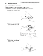
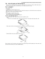
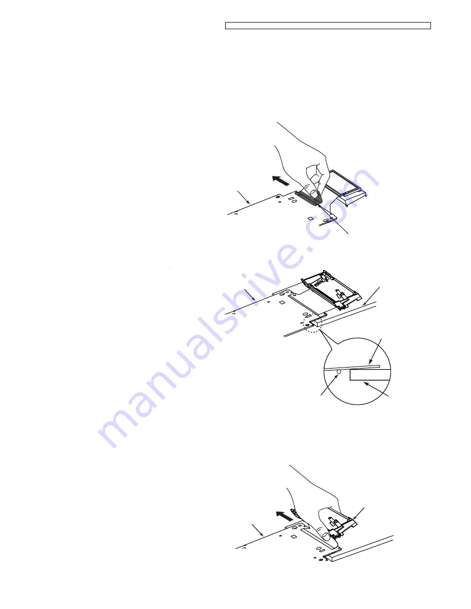
Peel off the arak tape at the front of P.C.board.
P. C. board
Arak Tape
1
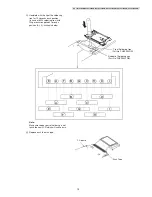
Peel off the HSC (Heat Seal Connector) from
the P.C. board, in the direction of the arrow.
Use some IPA alcohol to gently remove glue
stain on the P.C. board.
P. C. board
LCD
3
2
P. C. board
P. C. board
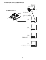
Platform
Platform
Crystal
Side View
Note :
The platform height must be able
to protect crystal at the bottom of
the P.C.board.
.
(Crystal height = 2mm)
Turn over the P.C. board and place a platform
as shown to protect the crystal at the bottom
side of the P.C.board.

