7 CIRCUIT OPERATIONS
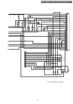
7.1. Telephone Line Interface and Pulse Dial Circuit
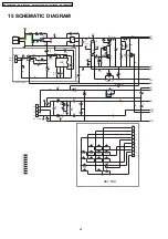
When the hook switch SW1 is ON (off-hook), the circuit is closed, and current is supplied to the base of Q2 via the diode bridge
D17 and Q2 is On
→
Q1 is ON (OFF-HOOK condition).
Q1 and Q2 are the dial pulse generating circuits, and are driven by the DIALER (IC1), when the DIALER Pin 10 of IC1 is LOW
→
Q2 is OFF and Q1 is OFF (break). If port Pin 10 is HIGH
→
Q2 is ON
→
Q1 is ON (make).
7.2. Tone Dial Circuit
Function:
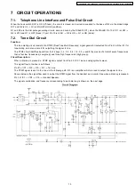
The tone dialing circuit consists of a DTMF (Dual Tone Multi Frequency) signal generator (outputted from Pin 25 of the IC1) for
tone dialing, and also a circuit for outputting the signal to line.
The DTMF circuit identifies inputs from the 12 keys (1, 2, 3, 4, 5, 6, 7, 8, 9, 0,
and #) by means of a total of seven frequencies,
that is four low frequencies (Low group) and three high frequencies (High group).
Circuit Description:
When a dial key is pressed, a DTMF signal is output from Pin 25 of IC1 as an analog synthetic wave.
The signal flow to the line is as follows.
Pin 25 of IC1
→
Q3
→
R9
→
Q1
→
Tel Line.
The DTMF signal is sent to the line via the following path. Q3 is an amplifier which is used to output the signal to line.
Shown below is the signal flow used to output the DTMF signal from the handset as a monitor tone when a dial key is pressed.
Pin 3 of IC1
→
VR1
→
C15
→
Handset Speaker.
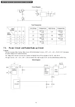
The signal combination and frequency corresponding to each dial key is shown on the next page.
13
KX-TS2350CAB / KX-TS2350CAC / KX-TS2350CAH / KX-TS2350CAR / KX-TS2350CAW


