background image

2.2 Programming

38

Programming Guide

2.2.8

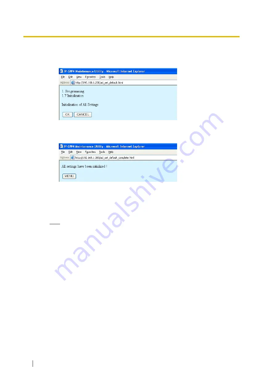
Initialisation

1.

Click 

1.7 Initialization

 in the main menu.

2.

Click 

OK

 to initialise all parameters to the default values.

To abort initialisation, click 

CANCEL

. You will be taken back to the main menu (see "2.1 

Main Menu for the Administrator").

Initialisation has to be followed by a reboot to make the default values effective for the 
parameters indicated with "

#

" (e.g., IP address of the VoIP Gateway Card). If not followed 

by a reboot, the current setting values will remain effective instead.

3.

Click 

MENU

 to return to the main menu (see "2.1 Main Menu for the Administrator").

4.

Refer to "2.5.1 Reboot" and finish the reboot.

Note

If you have forgotten the IP address or log-in password of the VoIP Gateway Card, follow 
the procedure detailed in "C1 Initialising the VoIP Gateway Card" of the VoIP Gateway 
Card Getting Started to return all settings to the factory default.

Summary of Contents for KX-TDA3480

Page 1: ...4 Channel VoIP Gateway Card Programming Guide Thank you for purchasing the Panasonic 4 Channel VoIP Gateway Card KX TDA3480 KX TDA0484 Please read this manual carefully before using this product and save this manual for future use ...

Page 2: ...y 34 2 2 8 Initialisation 38 2 3 Maintenance 39 2 3 1 Status Control 39 2 3 2 Maintenance Settings 40 2 3 3 Diagnosis 42 2 3 4 Log Information 43 2 4 Data Management 44 2 4 1 Upload of Configuration Data 44 2 4 2 Download of Configuration Data 46 2 4 3 Upload of Address Translation Table 47 2 4 4 Download of Address Translation Table 49 2 5 Others 50 2 5 1 Reboot 50 2 5 2 Log Out 51 3 Installer Fu...

Page 3: ... IP GW4 Maintenance Utility Programming of the VoIP Gateway Card is carried out through a web programming utility called the IP GW4 Maintenance Utility This section provides the start up procedure for the IP GW4 Maintenance Utility ...

Page 4: ...crosoft is either a registered trademark or trademark of Microsoft Corporation in the United States and or other countries All other trademarks identified herein are the property of their respective owners Screen shots reprinted with permission from Microsoft Corporation 1 Run Internet Explorer from the Start menu 2 In the Address box of Internet Explorer type http 192 168 1 200 192 168 1 200 is t...

Page 5: ...um If you finish a programming session without logging out from the card e g quitting Internet Explorer or returning to the log in screen with the Back button of Internet Explorer you cannot log in again for the period of time specified by the parameter Programming Auto Disconnect Time default 10 min For the log out procedure and Programming Auto Disconnect Time setting refer to 2 5 2 Log Out 3 4 ...

Page 6: ...1 1 Starting the IP GW4 Maintenance Utility 6 Programming Guide ...

Page 7: ...Programming Guide 7 Section 2 Administrator Functions This section provides operating instructions for the IP GW4 Maintenance Utility when logged in as the Administrator ...

Page 8: ...2 1 Main Menu for the Administrator 8 Programming Guide 2 1 Main Menu for the Administrator The IP GW4 Maintenance Utility provides the following menu to a user logged in as the Administrator ...

Page 9: ...ranslation Table GW Entry 2 2 7 Address Translation Table DN2IP Entry 1 7 Initialization 2 2 8 Initialisation Menu Section Reference 2 1 Change RUN STOP status 2 3 1 Status Control 2 2 Maintenance Settings 2 3 2 Maintenance Settings 2 3 Diagnosis 2 3 3 Diagnosis 2 4 Log Information 2 3 4 Log Information Menu Section Reference 3 1 Upload of Configuration data PC VoIP Gateway 2 4 1 Upload of Configu...

Page 10: ...tions below At any time during the session you can Click ALL CLEAR to reset all parameters to the default values Click MENU to return to the main menu see 2 1 Main Menu for the Administrator Click LOGOUT to log out from the IP GW4 Maintenance Utility see 2 5 2 Log Out 3 Click OK You will see a confirmation screen Note If your entry contains an invalid value you will see an error screen Click OK an...

Page 11: ...t your network administrator 255 255 255 0 Any address is valid Default Gateway Specifies the default gateway IP address of the card For more information consult your network administrator 0 0 0 0 Same as the parameter IP Address except that the address 0 0 0 0 is allowed Parameter Description Default Value Range DHCP Server Specifies the use of a DHCP server For details refer to Detailed Explanat...

Page 12: ... settings consult your network administrator In addition it is also necessary to specify the values for the parameters under IP Address Settings as they will be assigned by the DHCP server Parameter Description Default Value Range HTTP Port No Specifies the port number for HTTP communications by the card Generally there is no need to change the default value 80 1 to 65535 Parameter Description Def...

Page 13: ...t all parameters to the default values Click MENU to return to the main menu see 2 1 Main Menu for the Administrator Click LOGOUT to log out from the IP GW4 Maintenance Utility see 2 5 2 Log Out 3 Click OK You will see a confirmation screen Note If your entry contains an invalid value you will see an error screen Click OK and try again with correct values 4 Confirm your entry and click OK To retur...

Page 14: ...n an H 323 protocol suite Generally there is no need to change the default value 1720 1 to 65535 H 245 Port No Specifies the port number for the H 245 protocol negotiation of channel usage and capabilities in an H 323 protocol suite Four consecutive ports starting with the specified port will be used by default 1721 to 1724 Generally there is no need to change the default value 1721 1 to 65532 RAS...

Page 15: ...G 723 1 G 729A G 711Mu G 711A Parameter Description Default Value Range Gatekeeper Specifies the use of a gatekeeper For details refer to Detailed Explanations Don t use Use Don t use Primary Gatekeeper IP Address Specifies the IP address of the primary gatekeeper 192 168 1 3 The following addresses are invalid Class D addresses Class E addresses Loopback addresses Primary Gatekeeper Port No Speci...

Page 16: ...gatekeeper When using a gatekeeper make sure to choose a compatible model For more information about gatekeeper compatibility with the card consult a certified dealer Gatekeeper Connection Checking Interval min 0 1440min Specifies the time in minutes between periodic checks of connection to the gatekeeper When the primary gatekeeper fails these checks can detect the failure In this case the connec...

Page 17: ... CLEAR to reset all parameters to the default values Click MENU to return to the main menu see 2 1 Main Menu for the Administrator Click LOGOUT to log out from the IP GW4 Maintenance Utility see 2 5 2 Log Out 3 Click OK You will see a confirmation screen Note If your entry contains an invalid value you will see an error screen Click OK and try again with correct values 4 Confirm your entry and cli...

Page 18: ...e ToS field by a hexadecimal number No default 00 to FF When voice signals are packetised and transmitted individual packets can take different paths through the network and arrive at the destination at varied timings This is referred to as jitter and it can cause degradation in speech quality To compensate for jitter problems the jitter buffer accumulates the packets temporarily for processing Th...

Page 19: ...ation feature G 168 Echo is the audible duplication of a caller s voice on the return path when echo exists the caller hears his or her own voice after some delay The echo canceller eliminates this echo Use Use Don t use G 723 1 VAD Voice Activity Detection Specifies the use of the VAD feature G 723 1 The VAD conserves bandwidth by detecting silent periods during a call and suppressing the packets...

Page 20: ...Method Original Specifies the use of the packet multiplexing feature during fax communications For details refer to Detailed Explanations Don t use Use Don t use DTMF Detection Level dB 20 0dB Specifies the level in decibels of DTMF detection Generally there is no need to change the default value 20 20 to 0 Parameter Description Default Value Range Bit 0 Bit 8 IP Header Version IHL Total Length 0 ...

Page 21: ...0 ms 40 ms 60 ms 90 ms G 711 87 2 kbps 79 5 kbps 75 6 kbps G 729A 31 2 kbps 23 5 kbps 19 6 kbps G 723 1 5 3 kbps 20 8 kbps 13 1 kbps 10 5 kbps G 723 1 6 3 kbps 21 9 kbps 14 1 kbps 11 6 kbps Bit 0 Bit 8 IP Header Version IHL Total Length Bit 15 Reserved Reserved Bit 32 IP Packet Type of Service DSCP 0 DSCP 1 DSCP 62 DSCP 63 0 0 1 1 0 0 1 1 0 0 1 1 0 0 1 1 0 0 1 1 0 1 0 1 Bit 0 Bit 8 IP Header Versi...

Page 22: ... the received encoded signals and then sends them to the PBX Note that when this feature is enabled the sending of packets is delayed by approximately 30 ms Therefore it is recommended that you disable this feature unless DTMF detection is necessary FAX Signal Detection When sending fax signals using a CODEC other than G 711 the signals cannot be received accurately at the destination because they...

Page 23: ...VoIP channel when using this feature The tables below show the amount of bandwidth required for one VoIP channel when this feature is in use and not in use Required Bandwidth for Fax Communication via LAN Required Bandwidth for Fax Communication via WAN PPP Point to Point Protocol Notes Fax communications cannot take place between the KX TDA3480 KX TDA0484 and KX TDA0480 VoIP Gateway Cards Fax com...

Page 24: ...n screen Note If your entry contains an invalid value you will see an error screen Click OK and try again with correct values 4 Confirm your entry and click OK To return to the previous screen click CANCEL Parameter Descriptions Dialling Settings The parameters indicated with must be changed while the VoIP Gateway Card is in the STOP status see 2 3 1 Status Control The changes do not have to be fo...

Page 25: ... to 10 Digit End Code Specifies the delimiter code to be used to signal the end of a dial number Generally there is no need to change the default value 0 to 9 Parameter Description Default Value Range Network CODEC of IP PBX The value of this parameter is set automatically as appropriate to the setting of the PBX There is no need to change the value Not applicable G 711 Mu Law G 711 A Law Paramete...

Page 26: ...n a Click the desired sort key and sort order from the Sort Option lists b Click SORT Delete the desired hunt pattern from the table at the bottom of the screen a Select the appropriate check box for the hunt pattern you want to delete b Click DELETE Click LOGOUT to log out from the IP GW4 Maintenance Utility see 2 5 2 Log Out 3 Click ENTRY A maximum of 16 hunt patterns can be created 4 Click OK Y...

Page 27: ... Value Range Hunt Pattern No Specifies the number for the hunt pattern to be created When changing the current settings of an existing hunt pattern first delete the hunt pattern and then re create with new values No default 1 to 16 Receive Leading Number Specifies the leading digits in received numbers by which to determine the hunt group to direct incoming calls For example to direct incoming cal...

Page 28: ...e incoming calls depending on the received numbers The following examples provide two different methods of hunt pattern programming Hunt Group Priority2 Specifies the hunt group to which incoming calls are directed when the VoIP gateway port assigned to Hunt Group Priority1 is busy 1 2 Parameter Description Default Value Range IP Network VoIP Gateway Card Port 1 PBX PBX Code 950 Extn Group A Extn ...

Page 29: ...onfiguration no call can be routed to extension group B Hunt Group Hunt Pattern Entry Port 1 Port 2 Hunt Group Hunt Group 1 Hunt Group 1 Hunt Pattern No 1 Receive Leading Number 9 Hunt Group Priority1 1 Hunt Group Priority2 IP Network VoIP Gateway Card Port 1 PBX PBX Code 950 Extn Group A Extn 101 Extn 199 Channel 1 Channel 2 Extn Group B Extn 201 Extn 299 Port 2 Channel 1 Channel 2 Dials 950 101 ...

Page 30: ...le VoIP gateway port to individual extension groups A and B for making outgoing calls With this programming each extension group A and B can have a port for its exclusive use The VoIP gateway port the extension group A uses to make outgoing calls port 1 The VoIP gateway port the extension group B uses to make outgoing calls port 2 Port 1 Port 2 Hunt Group Hunt Group 1 Hunt Group 2 Hunt Pattern No ...

Page 31: ...y 3 Assign each parameter referring to the descriptions below At any time during the session you can Click MENU to return to the main menu see 2 1 Main Menu for the Administrator Click PREVIOUS to return to the previous screen Sort the gateway entries in the table at the bottom of the screen a Click the desired sort key and sort order from the Sort Option lists b Click SORT ...

Page 32: ...CEL Parameter Descriptions GW Entry The parameters indicated with must be changed while the VoIP Gateway Card is in the STOP status see 2 3 1 Status Control The changes do not have to be followed by a reboot to become effective The parameters below are used to create gateway entries for both local and remote cards on the network as a preliminary step to programming the address translation table DN...

Page 33: ...Specifies the number of the gateway group to which the gateway entry belongs Grouping is useful when there is more than one card installed in a PBX because it allows you to use the automatic route redirection feature For details refer to Detailed Explanations in the next section 2 2 7 Address Translation Table DN2IP Entry 0 0 belong to no group 1 to 256 Parameter Description Default Value Range ...

Page 34: ...Main Menu for the Administrator Click PREVIOUS to return to the previous screen Sort the DN2IP entries in the table at the bottom of the screen a Click the desired sort key and sort order from the Sort Option lists b Click SORT Delete the desired DN2IP entry from the table at the bottom of the screen a Select the appropriate check box for the DN2IP entry you want to delete b Click DELETE Click LOG...

Page 35: ...ranslation Table of the VoIP Gateway Card Getting Started Note If you are using a gatekeeper create the DN2IP entries only for the local card In this case you can create up to four DN2IP entries per card Note that if you are not using a gatekeeper there is no maximum number of DN2IP entries Parameter Description Default Value Range Leading Number Specifies the leading digits in dialled numbers by ...

Page 36: ...ds B and C installed in PBX 2 Example of Gateway Entry Programming Through gateway entry programming cards B and C are grouped into a single gateway group GW No Group No Specifies the number of the destination gateway or gateway group GW No 0 Group No 1 GW No 0 to 511 Group No 1 to 256 Parameter Card A Card B Card C GW No 0 1 2 Comment IP GW Card A IP GW Card B IP GW Card C IP Address 192 168 1 1 ...

Page 37: ... card B are busy card A automatically redirects the call to card C This is possible because by grouping PBX 1 sees PBX 2 as having a combined set of eight channels not two separate sets of four channels Note The automatic route redirection feature cannot be used in a network where a gatekeeper is used For details about gatekeeper settings refer to Gatekeeper Settings in 2 2 2 H 323 Parameters Para...

Page 38: ...t values effective for the parameters indicated with e g IP address of the VoIP Gateway Card If not followed by a reboot the current setting values will remain effective instead 3 Click MENU to return to the main menu see 2 1 Main Menu for the Administrator 4 Refer to 2 5 1 Reboot and finish the reboot Note If you have forgotten the IP address or log in password of the VoIP Gateway Card follow the...

Page 39: ...executing STOP This will allow you to place the card in the STOP status even when there are ongoing calls At any time during the session you can Click MENU to return to the main menu see 2 1 Main Menu for the Administrator Click LOGOUT to log out from the IP GW4 Maintenance Utility see 2 5 2 Log Out 3 Click OK You will see a confirmation screen 4 Click OK You will see a result screen Note If the o...

Page 40: ... Out 3 Click OK You will see a confirmation screen Note If your entry contains an invalid value you will see an error screen Click OK and try again with correct values 4 Confirm your entry and click OK To return to the previous screen click CANCEL Parameter Descriptions Username Password Settings The parameters indicated with must be changed while the VoIP Gateway Card is in the STOP status see 2 ...

Page 41: ...ated If the specified period of time passes with no programming input programming will automatically be terminated This prevents problems caused by continuation of log in status in cases such as being unable to log out due to the sudden failure of a PC 10 1 to 30 Parameter Description Default Value Range Periodic Diagnosis Time Interval min 0 1440min Specifies the time in minutes between periodic ...

Page 42: ...th the operation of the VoIP Gateway Card 1 Click 2 3 Diagnosis in the main menu 2 Click DIAGNOSIS to carry out the self diagnostic programme 3 Do one of the following Click DIAGNOSIS to carry out the self diagnostic programme again Click MENU to return to the main menu see 2 1 Main Menu for the Administrator Click LOGOUT to log out from the IP GW4 Maintenance Utility see 2 5 2 Log Out ...

Page 43: ...mation is provided for engineer use only However in the case that a need should arise this section provides the procedure for collecting the log information 1 Click 2 4 Log Information in the main menu 2 Click OK Log information is displayed 3 Click Download All to download the log information ...

Page 44: ... menu 2 Click Browse and choose a file to upload At any time during the session you can Click MENU to return to the main menu see 2 1 Main Menu for the Administrator Click LOGOUT to log out from the IP GW4 Maintenance Utility see 2 5 2 Log Out 3 Click UPLOAD PC VoIP Gateway The upload operation starts Notes If the upload operation is executed while the card is in the RUN status you will see an err...

Page 45: ...BOOT to make the changes effective now You will see a confirmation screen Refer to 2 5 1 Reboot and finish the reboot Click OK to return to the previous screen without rebooting However remember to reboot the card at the end of the programming session to make changes effective ...

Page 46: ...n data VoIP Gateway PC in the main menu 2 Click DOWNLOAD At any time during the session you can Click MENU to return to the main menu see 2 1 Main Menu for the Administrator Click LOGOUT to log out from the IP GW4 Maintenance Utility see 2 5 2 Log Out 3 Specify the file name and the folder in which to save the file ...

Page 47: ...ain Menu for the Administrator Click LOGOUT to log out from the IP GW4 Maintenance Utility see 2 5 2 Log Out 3 Click UPLOAD PC VoIP Gateway The upload operation starts Notes If the upload operation is executed while the card is in the RUN status you will see an error screen Click Change RUN STOP status Screen and place the card in the STOP status see 2 3 1 Status Control and then upload the data a...

Page 48: ...BOOT to make the changes effective now You will see a confirmation screen Refer to 2 5 1 Reboot and finish the reboot Click OK to return to the previous screen without rebooting However remember to reboot the card at the end of the programming session to make changes effective ...

Page 49: ... data VoIP Gateway PC in the main menu 2 Click DOWNLOAD At any time during the session you can Click MENU to return to the main menu see 2 1 Main Menu for the Administrator Click LOGOUT to log out from the IP GW4 Maintenance Utility see 2 5 2 Log Out 3 Specify the file name and the folder in which to save the file ...

Page 50: ...BOOT To return to the main menu click CANCEL see 2 1 Main Menu for the Administrator Note If the reboot operation is not successful you will see an error page 3 To continue programming click LOGIN Screen and log in again You will see the log in screen see 1 1 Starting the IP GW4 Maintenance Utility ...

Page 51: ...2 5 Others Programming Guide 51 2 5 2 Log Out 1 Click LOGOUT in the main menu 2 Click OK to log out ...

Page 52: ...2 5 Others 52 Programming Guide ...

Page 53: ...Programming Guide 53 Section 3 Installer Functions This section provides operating instructions for the IP GW4 Maintenance Utility when logged in as the Installer ...

Page 54: ... Maintenance Data Management Others Menu Section Reference 1 1 Change RUN STOP status 3 2 1 Status Control 1 2 Maintenance Settings 3 2 2 Maintenance Settings Menu Section Reference 2 1 Upload of Firmware data PC VoIP Gateway 3 3 1 Upload of Firmware Data 2 2 Handling of Firmware Page 3 3 2 Handling of Firmware Page Menu Section Reference REBOOT 3 4 1 Reboot LOGOUT 3 4 2 Log Out ...

Page 55: ...n executing STOP This will allow you to place the card in the STOP status even when there are ongoing calls At any time during the session you can Click MENU to return to the main menu see 3 1 Main Menu for the Installer Click LOGOUT to log out from the IP GW4 Maintenance Utility see 3 4 2 Log Out 3 Click OK You will see a confirmation screen 4 Click OK You will see a result screen Note If the ope...

Page 56: ... see 3 4 2 Log Out 3 Click OK You will see a confirmation screen Note If your entry contains an invalid value you will see an error screen Click OK and try again with correct values 4 Confirm your entry and click OK To return to the previous screen click CANCEL Parameter Descriptions Username Password Settings Parameter Description Default Value Range Username for Installer Installer level log in ...

Page 57: ...3 2 Maintenance Programming Guide 57 Program Version Parameter Default Value Range Program Version Display only ...

Page 58: ...ick 2 1 Upload of Firmware data PC VoIP Gateway in the main menu 2 Do the following to upload the firmware data to the temporary buffer in the VoIP Gateway Card a Click Browse and choose a file to upload At any time during the session you can Click MENU to return to the main menu see 3 1 Main Menu for the Installer Click LOGOUT to log out from the IP GW4 Maintenance Utility see 3 4 2 Log Out b Cli...

Page 59: ...de for Select Page b Click OK You will see a confirmation screen c Click OK 4 Do one of the following Click REBOOT to start up the VoIP Gateway Card with the updated page and confirm that the upload operation has been carried out successfully You will see a reboot confirmation screen Refer to 3 4 1 Reboot and finish the reboot Note After the reboot the card starts up with the updated page temporar...

Page 60: ...dated page from NEW to Main Operation Mode After the previous step with or without a reboot the firmware status of the updated page is still NEW To set the updated page as the active page on startup you must change its firmware status to Main Operation Mode For instructions refer to 3 3 2 Handling of Firmware Page The following is a sample image of the screen in which you can set the active page o...

Page 61: ...Click LOGOUT to log out from the IP GW4 Maintenance Utility see 3 4 2 Log Out Note Do not click Empty as it is an option provided for engineer use only 3 Click the option for the page in the NEW status for Select Page to specify it as the target page of the operation 4 Click OK You will see a confirmation screen 5 Click OK You will see a result screen 6 Click OK You will be taken back to the Handl...

Page 62: ... Main Operation Mode The exception is when the card undergoes a reboot after a firmware data upload operation in this case the card starts up with the page in the NEW status This is for the purposes of confirming the result of the upload operation If you reboot again the card starts up with the page in the Main Operation Mode status To set the updated page as the active page on startup you must ch...

Page 63: ...REBOOT To return to the main menu click CANCEL see 3 1 Main Menu for the Installer Note If the reboot operation is not successful you will see an error page 3 To continue programming click LOGIN Screen and log in again You will see the log in screen see 1 1 Starting the IP GW4 Maintenance Utility ...

Page 64: ...3 4 Others 64 Programming Guide 3 4 2 Log Out 1 Click LOGOUT in the main menu 2 Click OK to log out ...

Page 65: ...Programming Guide 65 Index ...

Page 66: ...GW Entry 31 32 H H 225 Port No 14 H 245 Port No 14 H 323 13 H 323 Detailed Settings 13 Handling of Firmware Page 61 Host Name 12 HTTP Port Number Settings 12 Hunt Pattern for Incoming Calls 26 I Initialisation 38 Inter Digit Time 25 IP Address 11 IP Address Settings 11 IP Header 18 20 J Jitter Buffer Settings 18 L LAN 21 23 LAN Disconnect Threshold Time 12 Log Information 43 Log Out 51 64 M Main M...

Page 67: ...ming Guide 67 Upload of Firmware Data 58 Username Password Settings 40 56 V VAD Voice Activity Detection 19 Voice CODEC Settings 15 Voice Communication Detailed Settings 17 VoIP Gateway IP PBX Interface Settings 24 ...

Page 68: ...pyrighted by Panasonic Communications Co Ltd PCC You may print out this manual solely for internal use with this model Except above you may not reproduce this manual in any form in whole or part without the prior written consent of PCC 2003 Panasonic Communications Co Ltd All Rights Reserved PSQX3123YA KK1103AH1024 ...

Reviews: