


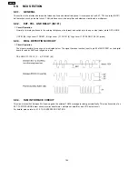


6.6. MODEM SECTION
6.6.1. FUNCTION
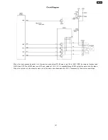
The unit uses a 1 chip modem (IC505) that serves as an interface between the control section for FAX transmission and reception
and the telephone line. During a transmitting operation, the digital image signals are modulated and sent to the telephone line.
During a receiving operation, the analog image signals which are received via the telephone line are demodulated and converted
into digital image signals. The communication format and procedures for FAX communication are standardized by CCITT. This 1
chip modem (IC505) has hardware which sends and detects all of the necessary signals for FAX communication.
It can be controlled by writing commands from the CPU (IC501: inside ASIC) to the register in the modem (IC505).
This modem (IC505) also sends DTMF signals, generates a call tone (from the speaker), and detects a busy tone and dial tones.
Overview of Facsimile Communication Procedures (CCITT Recommendation):
1. ON CCITT (International Telegraph and Telephone Consultative Committee)
The No. XIV Group of CCITT, one of the four permanent organizations of the International Telecommunications Union (ITU),
investigates and make recommendations on international standards for facsimiles.
2. Definition of Each Group
·
Group I (G1)
Official A-4 size documents without using formats which reduce the band width of a signal are sent over telephone lines.
Determined in 1968.
Transmission for about 6 minutes at a scanning line density of 3.85 lines/mm.
·
Group II (G2)
Using reduction technology in the modulation/demodulation format, an A-4 size document is sent at an official scanning line
density of 3.85 lines/mm for about 3 minutes.
Methods to suppress redundancy are not used.
Determined in 1976.
·
Group III (G3)
Method of suppressing redundancy in the image signal prior to modulation is used. An A-4 size document is sent within
about one minute.
Determined in 1980.
·
Group IV (G4)
Transmission is via the data network. A method is provided for suppressing redundancy in signals prior to transmission, and
error-free reception of transmission is possible.
The scope of these facsimile applications is not limited simply to transmission of written statements. Through symbiotic
linkages with other communication methods, it can be expected to expand to include integrated services.
155
KX-FP101
Summary of Contents for KX-FP105BX
Page 36: ...1 11 CCITT No 1 Test Chart Actual size 8 KX FP101 ...
Page 38: ...1 12 2 CONTROL PANEL 10 KX FP101 ...
Page 58: ...2 3 3 TROUBLESHOOTING ITEMS TABLE 30 KX FP101 ...
Page 59: ...2 3 3 1 Simple Check List 31 KX FP101 ...
Page 61: ...2 Document JAM 33 KX FP101 ...
Page 65: ...6 Paper JAM 7 Multiple feed and skew 37 KX FP101 ...
Page 68: ...Fig C 12 A blank page is received 40 KX FP101 ...
Page 72: ...2 3 3 3 1 Defective facsimile section 1 Transmit problem 44 KX FP101 ...
Page 80: ...52 KX FP101 ...
Page 81: ...53 KX FP101 ...
Page 82: ...54 KX FP101 ...
Page 83: ...55 KX FP101 ...
Page 84: ...56 KX FP101 ...
Page 85: ...57 KX FP101 ...
Page 86: ...58 KX FP101 ...
Page 87: ...59 KX FP101 ...
Page 92: ...2 3 3 4 1 Digital Block Diagram 64 KX FP101 ...
Page 95: ...I O and Pin No Diagram 67 KX FP101 ...
Page 97: ...69 KX FP101 ...
Page 98: ...NG Example 70 KX FP101 ...
Page 99: ...2 3 3 4 2 Check the Status of the Digital Board 71 KX FP101 ...
Page 101: ...Note Inside the digital board 73 KX FP101 ...
Page 105: ...2 Troubleshooting Flow Chart 77 KX FP101 ...
Page 107: ...2 3 3 7 Operation Panel Section 1 No key operation 2 No LCD indication 79 KX FP101 ...
Page 110: ...2 3 3 9 CIS Contact Image Sensor Section Refer to 6 4 4 SCANNING BLOCK 82 KX FP101 ...
Page 111: ...83 KX FP101 ...
Page 112: ...2 3 3 10 Thermal Head Section Refer to 6 4 3 THERMAL HEAD 84 KX FP101 ...
Page 125: ...2 4 7 3 PRINTOUT EXAMPLE 97 KX FP101 ...
Page 126: ...98 KX FP101 ...
Page 129: ...2 5 3 PRINT TEST PATTERN 1 Platen roller Reference pattern 101 KX FP101 ...
Page 130: ...2 Left margin Top margin Reference pattern 102 KX FP101 ...
Page 131: ...3 Thermal head 1 dot Reference pattern 103 KX FP101 ...
Page 154: ...6 3 2 MEMORY MAP 126 KX FP101 ...
Page 166: ...138 KX FP101 ...
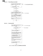
Page 176: ...6 4 6 3 2 Transmitting documents 6 4 6 3 3 Receiving FAX 148 KX FP101 ...
Page 177: ...6 4 6 3 4 Copying 149 KX FP101 ...
Page 212: ...12 1 MEMO KX FP101 184 ...
Page 214: ...13 1 MEMO KX FP101 186 ...
Page 216: ...14 1 MEMO KX FP101 188 ...
Page 218: ...15 1 MEMO KX FP101 190 ...
Page 220: ...16 1 MEMO KX FP101 192 ...
Page 221: ...17 TERMINAL GUIDE OF THE IC S TRANSISTORS AND DIODES 193 KX FP101 ...
Page 222: ...18 FIXTURES AND TOOLS 194 KX FP101 ...
Page 223: ...19 CABINET MECHANICAL AND ELECTRICAL PARTS LOCATION 19 1 OPERATION PANEL SECTION 195 KX FP101 ...
Page 224: ...19 2 UPPER CABINET SECTION 196 KX FP101 ...
Page 225: ...19 2 1 PICK UP BASE SECTION 197 KX FP101 ...
Page 226: ...19 3 LOWER P C B SECTION 198 KX FP101 ...
Page 227: ...19 4 MOTOR SECTION 199 KX FP101 ...
Page 228: ...19 5 ACTUAL SIZE OF SCREWS AND WASHER 200 KX FP101 ...
Page 229: ...20 ACCESSORIES AND PACKING MATERIALS 201 KX FP101 ...