background image

Display Panel Instructions

15

Imprinter menu

Depending on the setting of the “Counter setting menu”, the page number of the scanned document will be
printed. The post-imprinter option (KV-SS028) is required. If a host computer is connected, there may be settings
required on the host computer as well.

No.

Item

LCD display

Contents

Page

11

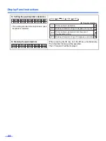
Setting the post-
imprinter data

Post Imprint

Allows for the selection of the printing content using 
an imprinter.
The imprinter will print on the reverse side of the 
document after scanned.

23

12

Setting the post-
imprinter position

Post Position

Allows for the selection of the printing position using 
a post-imprinter.

23

13

Setting the post-
imprinter font style

Post Font

Allows for the selection of the printing font style 
using a post-imprinter.

23

14

Setting the post-
imprinter orientation

Post 
Orientation

Allows for the selection of the printing orientation 
using a post-imprinter.

24

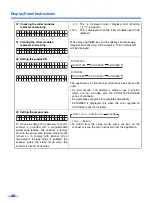
15

Cleaning the post-
imprinter

Post Cleaning

Cleans all nozzles of the post-imprinter by ejecting 
ink.

24

Summary of Contents for KV-S3105C

Page 1: ...stallation manual enclosed with this unit Please carefully read these instructions the enclosed installation manual and maintenance manual Keep all documentation in a safe place for future reference K...

Page 2: ...o work When using the scanner with other SCSI devices connected by daisy chain connection it is not guaranteed to work As an ENERGY STAR Partner Panasonic has determined that this product meets the EN...

Page 3: ...4 Clearing Paper Jams 36 Removing paper jams from the feed part 36 Removing paper jams from exit path 36 If the paper cannot be removed by pulling it forward 36 Cleaning the Unit 37 Outside of the sca...

Page 4: ...d be used only with a power cord that is supplied by the manufacturer Power Source WARNING 220 240 V equipment A certified power supply cord has to be used with this equipment The relevant national in...

Page 5: ...ere electrical shock if the cut off plug is inserted into any 13 amp socket If a new plug is to be fitted please observe the wiring code as shown below If in any doubt please consult a qualified elect...

Page 6: ...Notice 6 Caution Labels...

Page 7: ...items on the unit Do not place the unit in an area where there is a lot of smoke dust chemical fumes or vibration Do not leave the power cord plugged into the AC outlet if the unit will not be used f...

Page 8: ...operate or place the unit in a vertical position Do not place the unit near a heating appliance or an air conditioning vent Do not place the unit in a room with extremely high or low humidity Do not p...

Page 9: ...urface of the disc Do not leave the disc out of its protective case Do not leave the disc in direct sunlight or near heat sources Do not place heavy objects on the disc case or drop the case To clean...

Page 10: ...on Exit tray Post Imprinter Top door Used for attaching the post imprinter unit ADF selector To prevent double feeding adjust the lever to feed the scanning documents properly See page 32 Paper path s...

Page 11: ...ts HOPPER 3 1 sheet Press to exit from the setting section and return to the ready status Also this function can change the dis play language Used to start or stop scanning a docu ment SCAN COUNTER IM...

Page 12: ...0 or 1 sheet with 17 lbs paper according to the number of sheets to be scanned The hopper position is changeable only when Ready is displayed on the LCD 1 Press the HOPPER 1 key to set the hopper to 1...

Page 13: ...de brightness B Brightness Selection for density when scanning the back side of a document 19 08 Back side image emphasis B Image Emphasis Selection for emphasis when scanning the back side of a docum...

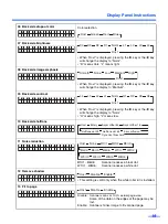
Page 14: ...saved If Default is selected all of the scanning conditions will return to the default values 21 No Item LCD display Contents Page 01 Select the counter displayed on the LCD Display Counter Choose to...

Page 15: ...ting content using an imprinter The imprinter will print on the reverse side of the document after scanned 23 12 Setting the post imprinter position Post Position Allows for the selection of the print...

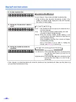
Page 16: ...synchronous transfer rate to 10 Mbytes sec if the computer has failed to recognize the scanner or the scanner fails to operate properly 25 06 Checking the roller cleaning warning Clean Roller Warning...

Page 17: ...the right is an example of a setting for the B Contrast 4 Press the HOME key to return to the Ready display or another menu key to go to another menu In steps 2 or 3 you can change to the desired menu...

Page 18: ...dark L means light 03 Front side image emphasis When Host is displayed pressing the 1 key or the 2 key will change the display to Medium 04 Front side contrast When Host is displayed pressing the 1 ke...

Page 19: ...en the white roller kit is installed 13 Fit to page Disable Scanner scans at 100 actual page size Some of the data on the edges of the page may be lost Enable Scanner shrinks image to fit scanned page...

Page 20: ...zzer When the scanner detects double feeding it will sound a buzzer the power indicator will light red and it will continue scanning After completing scanning the scanner will display double feeding w...

Page 21: ...saved in the memory selected in the Save scanning settings Select memory Completed will be displayed after saving 19 Load scanning setting If you use the 1 key or the 2 key to select Memory 1 or Memo...

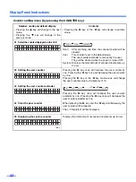
Page 22: ...e 1 key once will increase the user counter by one Pressing the 2 key once will decrease the user counter by one Pressing the 1 key or the 2 key continuously will change the user counter value by incr...

Page 23: ...printing starts from the top of the document If 0 character is set printing starts from 10 0 mm The millimeter value displayed is an approximation The length per character varies depending on the 04 o...

Page 24: ...usly Post Imprinter Cleaning will be executed Then Completed will be displayed 1 4 P o s t O r i e n t a t i o n H o s t Host 0o 90o 180o 270o A B AB Rotates character string 90 degrees and prints Pri...

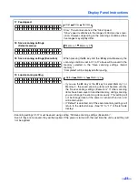
Page 25: ...ble Setting the wide SCSI will be activated after turning the power off and turning it on again 05 Setting the transfer rate When the wide SCSI setting is disable When the wide SCSI setting is enable...

Page 26: ...splayed only when the color upgrade kit KV SS029 option is installed 09 Setting the sleep mode To conserve energy and operating cost this scanner is provided with a programmable power save feature The...

Page 27: ...hen Ready will be displayed This will be displayed after setting scanning to start with a host computer If the document is set and the START key is pressed scanning will start This will be displayed w...

Page 28: ...shaped documents Tracing paper Thermal paper When scanning is not performed properly try the following methods Set the feed speed to Slow Scan the documents by manual feeding Set the paper path selec...

Page 29: ...lder will need to be separated 1 Fan the stack of documents to sepa rate all the edges 2 Hold both ends and bend the docu ments as shown in the illustration 3 To flatten the documents hold firmly and...

Page 30: ...hem in the direction of the arrow until they stop Be sure to place the documents on the hopper as shown in the diagram at the right The amount of documents should not exceed the limit mark on the docu...

Page 31: ...uired 6 When using paper longer than letter size pull out the hopper extension tray from the hopper and the exit tray stop per from the front door as shown in the diagram at the right When scanning sh...

Page 32: ...o function properly If double feed alarm beeps frequently change the ADF selector Setting Position Status 1 When double feeding occurs at the paper feed component 2 When double feeding occurs frequent...

Page 33: ...cument When printing the control sheet if the pattern falls in the area from the top side of the document to 25 mm adjust the printer Also copy the control sheet so that the pattern lies in the center...

Page 34: ...r hand pull the front door release towards you Then open the front door completely The front door now opens slowly 2 Using your finger slide the lower reference plate to the right 1 and turn it over 2...

Page 35: ...plate does not rotate after turning it over 4 Close the front door Push the front door down slowly until it clicks into position Be sure not to close the front door when the reference plate is in the...

Page 36: ...t door now opens slowly Remove the jammed document and close the front door Push down both sides of the front door gently until it clicks into place Removing paper jams from exit path If jammed docume...

Page 37: ...rollers sensors and double feed detectors if paper jamming or double feeding occurs frequently See pages 38 42 Clean the scanning section glasses and reference plates when black or white lines appear...

Page 38: ...leaning the rollers When the display shows Warning Clean Roller follow the steps below to clean the rollers 1 Turn the power off 2 Using your hand pull the front door release towards you The front doo...

Page 39: ...6 Close the retard roller cover 7 Use the roller cleaning paper to wipe off the dirt on the surfaces of six drive rollers 8 Use the roller cleaning paper to clean the surface of six free rollers Wipe...

Page 40: ...aces of the drive rollers and free rollers all the way around them proceeding from one end to the other in the directions of the arrows shown in the diagram to the right 12 Close the back door 13 Afte...

Page 41: ...nd reference plates using the roller cleaning paper When the reference plate slides toward right during cleaning push the reference plate at the left side lightly and slide it to the left until it is...

Page 42: ...ck door by pulling the back door release and open the post imprinter door 5 Also remove the dirt on the document sensors using included blower 6 Close all doors How to clean the sensors and double fee...

Page 43: ...release towards you The front door now opens slowly 3 Push down the two green levers at both ends of the paper feed roller mod ule to avoid breaking the green levers When moving the green levers do no...

Page 44: ...paper feed roller mod ule 6 Install the new paper feed roller mod ule with its gear on the right Insert the paper feed roller cover into the paper feed roller hole before attaching the bearings into...

Page 45: ...lace After installing the paper feed roller mod ule confirm that the feed rollers can be moved lightly in vertical direction Retard roller module 8 Set the ADF selector to the MANUAL position See page...

Page 46: ...module in the optional Roller Exchange Kit KV SS026 or Roller Exchange Kit for thin paper KV SS027 12 Install the new retard roller module by matching the groove of its right shaft with the groove of...

Page 47: ...of the arrow 14 Open the optional Roller Exchange Kit KV SS026 or Roller Exchange Kit for thin paper KV SS027 and take out the new Retard pad 15 Install the new retard pad by pressing it down until i...

Page 48: ...8 17 Close the front door Push down the front door slowly until it clicks into place 18 Set the ADF selector to the original position 19 Clear the Replace Roller Warning See page 26 Front door 2 5 4 1...

Page 49: ...ough 35 and 37 through 42 If the shading adjustment is carried out while these parts are still dirty it will not be possible to eliminate the lines that form on the scanned images Shading adjustment p...

Page 50: ...shading restarts and the LCD displays as shown on the right 8 The shading is complete when the LCD displays as shown on the right 9 Press the HOME key The LCD display returns to Ready Note If you need...

Page 51: ...quired Original Scanner Carton Packing Materials 1 Disconnect your scanner from the electrical outlet and the interface cable 2 Remove the exit tray guides exit tray stopper from the scanner 3 Pack th...

Page 52: ...lor Binary Grayscale Color option Multistream Binary Gray Binary Color option Tonal gradation Binary mode Grayscale mode 8 bit 64 step gradation dither mode Error diffusion mode Image control Image em...

Page 53: ...0 V 0 5 A AC220 240 V Sleep mode 10 W AC100 120 V 11 W AC220 240 V Operating Environment Operating temperature and humidity 15 C to 30 C 59 F to 86 F 20 to 80 RH Storage Environment Storage temperatur...

Page 54: ...he device manager s property Refer to the Installation Manual on page 24 The same ID number is used for the scanner and the other device Use the different SCSI ID numbers for each devices See page 25...

Page 55: ...cument guides properly to the size of the document to be scanned Right and left sides of the document to be scanned are not the same in height because of curl and fold Remove curl and fold then reduce...

Page 56: ...ter adheres to the reference plates F and B Clean the reference plates F and B See page 41 The document is jammed Open the front door and remove the jammed paper Then clean all of the rollers See page...

Page 57: ...of the rollers See page 38 When U16 JAM occurs fre quently the document sensor is dirty Clean the document sensors and reflectors See page 42 The document is jammed Open the front and back doors and r...

Page 58: ...e post imprinter door The interface is not installed properly Install the interface board again A user non serviceable error has occurred Consult with a service represen tative Call technical support...

Page 59: ...tor 42 Drive roller 39 40 E Energy Star 2 Exit document guides 10 31 Exit stopper 31 51 Exit tray 10 Exit tray stopper 10 31 51 F Fan exhaust vent 10 37 Feed rollers 45 Free rollers 39 40 Front door 1...

Page 60: ...7 R Reference plate 34 41 Reflectors 42 Repacking 51 Replacing consumables 43 Retard pad 47 Retard roller 39 Retard roller cover 39 46 47 Retard roller module 46 Roller cleaning paper 38 S SCAN key 1...

Page 61: ...of North America Two Panasonic Way Secaucus New Jersey 07094 Panasonic Canada Inc 5770 Ambler Drive Mississauga Ontario L4W 2T3 Matsushita Electric Industrial Co Ltd http www panasonic co jp global 2...

Reviews: