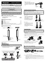
INSTRUCTION MANUAL
Contact-Type Digital Displacement Sensor / Sensor Head Air-Driven Type
+*6Ƒ$&
MJE-HGSAC No.0074-51V
Thank you very much for purchasing Panasonic products. Read this Instruction Man-
ual carefully and thoroughly for the correct and optimum use of this product. Kindly
keep this manual in a convenient place for quick reference.
W A R N I N G
Ɣ
Never use this product as a device for personnel protection.
Ɣ
When using devices for personnel protection, use products that meet the laws
and standards for personnel protection that apply in each region or country, such
as OSHA, ANSI and IEC.
This document provides a brief summary of mounting and other related information.
For detailed information, refer “
our web site (https://panasonic.net/id/pidsx/global) ”
1
STANDARDS AND REGULATIONS
Ɣ
This product conforms to the standards and regulations below.
<European Directives>
EMC Directive
2
CONTENTS OF PACKAGE
Sensor head
1 pc.
Mounting nut
1 pc.
Sensor head fastening wrench
1 pc.
Air tube clamp
1 pc.
Instruction Manual (English / Japanese, Chinese / Korean)
1 pc. each
General Information for Safety, Compliance, and Instructions(23 languages) 1 pc.
3
DESCRIPTION OF PARTS
When air is supplied
Spindle
Seal cap (Note)
Operation indicator
(Orange / Green)
Mounting nut
Air tube joint
Probe
Sensor head connection
cable connector
Note: The seal cap is provided as a maintenance part.
HG-SASCX5
(5 pcs. per set)
4
MOUNTING
Mounting on the housing
Ɣ 1RWHWKDWWKHPRXQWLQJGLUHFWLRQRIWKHSURYLGHGPRXQWLQJQXWGLႇHUVDFFRUGLQJ
to the thickness of the housing.
1.
Open a hole in the housing in which the
sensor head will be mounted
Thickness of
the housing
Mounting hole
ȭ
8H7
+0.015
0
mm
2.
Insert the sensor head into the hole you opened in the
housing, and fasten lightly with the provided mounting nut.
Thickness of the housing
A
B
HG-S1010-AC
,
HG-S1110-AC
6.5 to 10mm
10 to 12.5mm
A
Housing
B
Housing
Thread
Thread
Mounting nut with the
thread facing down
Mounting nut with the
thread facing up
Note: Please use within a the thickness of the housing range of 6.5~12.5mm.
Mounting nut
(Accessory)
3.
Fasten the sensor head.
Tighten the mounting nut with a wrench
while holding the sensor head in place
with the sensor head fastening wrench as
shown.Tighten to a torque of 12.5N·m or
less.
Mounting nut
(Accessory)
Sensor head
fastening wrench
(Accessory)
Connecting the sensor head connection cable
Ɣ :KHQDWWDFKLQJWKHFRQQHFWRUPDNHVXUHLWLV¿UPO\WLJKWHQHG,IORRVHWKHFRQ
-
QHFWRUPD\FRPHRႇDQGFDXVHDQHUURU
Ɣ
When disconnecting, always make sure that the fastening ring has been com-
pletely loosened before pulling out the cable.Risk of damage if you pull the cable
with excessive force (15N or more) with the fastening ring tightened.
Ɣ
Sensor head connection cables with an L-shaped connector cannot be used.
How to connect
1.
Insert the sensor head connection
cable into the connector for the
sensor head connection cable on
the sensor head.
2.
Turn the fastening ring on the sen-
sor head cable in the direction
VKRZQWR¿UPO\WLJKWHQWKHULQJ
1.
Insert
2.
Tighten
fastening ring
How to remove
1.
Turn the fastening ring on the sen-
sor head cable in the direction
shown to loosen the ring.
2.
Grasp each connector on the sen-
sor head connection cable and pull
out to remove.
2.
Pull out
1.
Loosen
Connecting the air tube
Ɣ :KHQFRQQHFWLQJWKHDLUWXEH¿UPO\VHFXUHLWZLWKWKHDLUWXEHFODPSSURYLGHG,I
the air tube is used without inserting or securing it properly, there is a danger that
WKHDLUWXEHPD\FRPHRႇZKLOHLWLVEHLQJXVHG
How to connect
1.
While loosening the air tube clamp, slide it from the tip of the air tube and then
release it when it reaches halfway through the tube.
2.
Insert the tip of the air tube until it reaches the root of the joint on the sensor
head
.
3.
Move the air tube clamp and secure the tip of the air tube.
4-mm-diameter air tube
Air tube clamp
(Accessory)
How to disconnect
1.
While loosening the air tube clamp, move it halfway
through the air tube.
2.
Grasp the sensor head and pull out the air tube.
Note: Take care not to lose the air tube clamp.
5
AIR CIRCUIT (RECOMMENDED)
Ɣ &UHDWHDQDLUFLUFXLWOLNHWKHRQHUHFRPPHQGHGVKRZQLQWKH¿JXUHEHORZDQG
if necessary, adjust the speed of the spindle with the speed control valve.
Air pressure source
Precision regulator
3-port solenoid valve
Speed control valve
Mist sep Regulator
Notes: 1) Supply clean air (free from moisture, oil, dust, or other foreign objects) to this product.
2) Air pressure may decrease, depending on the length of the air pipe from the air supply source or any pneu-
PDWLFFRPSRQHQWVVXFKDVQHHGOHYDOYHVVSHHGFRQWUROOHUVRUPLQL¿OWHUVWKDWDUHDGGHG7DNHFDUHWRHQ
-
VXUHWKDWDLUSUHVVXUHVXSSO\WRWKHSURGXFWLVVXႈFLHQW6HOHFWSQHXPDWLFFRPSRQHQWVVXLWDEOHIRUWKHVXS
-
plied air pressure.
3) The 3-port solenoid valve and speed control valve have their respective mounting directions. Mount each
valve in their correct direction by referring to the above diagram.
4)
$¿OWHUZLWKDUDWHG¿OWUDWLRQRI
ȣ
PRUOHVVDQGDPLVWVHSDUDWRUZLWKDUDWHG¿OWUDWLRQRI
ȣ
m or less are
recommended.


