


26
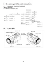
8.3.
Disassembly Procedure for the Unit
No.
Item
Fig.
Removal
1
Side Case L Unit
2 Screws (A)
2 Screws (B)
2 Locking Tabs
5 Screws (C)
2 Locking Tabs
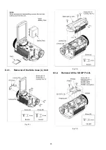
2
SD OP P.C.B.
2 Screws (D)
1 Hanging part
FP3901 (Flex)
FP3902 (Flex)
PS3901 (Connector)
3
Cover Board Unit
3 Screws (E)
1 Screw (F)
4
ESD P.C.B.
(HC-X900M only)
1 Screw (G)
1 Screw (H)
FP3201 (Flex)
ESD Angle
5
Top Case Unit
1 Screw (I)
2 Screws (J)
1 Screw (K)
1 Locking Tab
Sensor Window
1 Screw (L)
FP851 (Flex)
P6752 (Connector)
6
Front Case Unit
1 Screw (M)
FP6403 (Flex)
P7001 (Connector)
P7002 (Connector)
7
Lens Unit
FP6002 (Flex)
PS6011 (Connecto)
8
Side Case R Unit
(Fig. D10) 4 Screws (N)
2 Screws (O)
FP6004 (Flex)
P6001 (Connector)
P6302 (Connector)
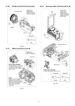
Rear Frame
9
Battery. Catcher
P.C.B.
(Fig. D11) PP6005 (Connector)
PS6751 (Connector)
Heat Radiation Sheet A
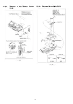
10 Main P.C.B.
(Fig. D12) 2 Screws (P)
3 Screws (Q)
FP6402 (Flex)
HDMI FPC
Main Heat Radiation Board
(Fig. D13) FP6001 (Flex)
FP6003 (Flex)
PP6006 (Connector)
PS7001 (Connector)
ESD FPC
Front FPC
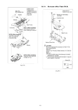
11 Flash P.C.B.
(Fig. D14) 2 Screws (R)
Bottom Frame Unit
12 Fan Motor
(Fig. D15) 1 Screw (S)
Fan Frame
Fan Damper
13 LCD Case T Unit
(Fig. D16) 2 Screws (T)
(Fig. D17) 2 Screws (U)
(Fig. D18) 6 Locking Tabs
FP901 (Flex)
FP902 (Flex)
Side Case R Unit
14 Monitor P.C.B.
(Fig. D19) FP903 (Flex)
FP904 (Flex)
FP906 (Flex)
3 Ribs
LCD Frame
(Fig. D20) Reflection Sheet
Light Guide Plate
15 LCD Panel Unit
(Fig. D21) Diffusion Sheet
Prism Sheet (B)
Prism Sheet (A)
(Fig. D22) LGP Holder
TP Spacer
LCD Case(B) Unit
16 Front P.C.B.
(Fig. D23) 1 Screw (V)
1 Screw (W)
FP6400 (Flex)
FP6402 (Flex)
17 Barrier Motor Unit
(Fig. D24) 1 Screw (X)
18 Barrier Case Unit
(Fig. D25) 4 Screws (Y)
4 Hooks
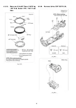
MF Ornament Unit
(Fig. D26) 3 Hooks
Flash
19 MF Peace /
MF Ring /
MF Holl Detect
FPC /
MF Front Case
(Fig. D27) 8 Hooks
20 EVF EXT P.C.B.
(Fig. D28) 2 Screws (Z)
1 Screw (a)
(Fig. D29) FP801 (Flex)
(Fig. D30) EVF FPC
(Fig. D31) 3 Locking Tabs
EVF Slide Frame
EVF Slide Case
(Fig. D32) 1 Screw (b)
FP802 (Flex)
2 Locking Tabs
EVF-LCD Peace
LCD
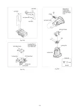
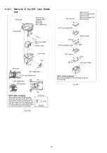
21 EVF Lens Holder
(Fig. D33) 2 Screws (c)
1 Locking Tab
EYES Cap
EVF Case
EVF Angle Knob
(Fig. D34) EVF Lens (C)
EVF Lens Spacer (BC)
EVF Lens (B)
EVF Lens Spacer (AB)
EVF Lens (A)
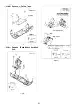
22 TOP Frame
(Fig. D35) 5 Screws (d)
23 Zoom Operation
Unit
(Fig. D36) 3 Screws (e)
(Fig. D37) 1 Screw (f)
1 Screw (g)
Photo Cushion
24 S/S Case Unit
(Fig. D38) 2 Screws (h)
1 Locking Tab
25 DC Jack P.C.B.
(Fig. D39) 2 Locking Tabs
S/S Button
(Fig. D40) 1 Screw (i)
1 Locking Tab
P6801 (Connector)
DC Battery. Wire
No.
Item
Fig.
Removal
Summary of Contents for HC-X900EB
Page 10: ...10 3 5 Formatting ...
Page 11: ...11 4 Specifications ...
Page 12: ...12 ...
Page 13: ...13 ...
Page 14: ...14 ...
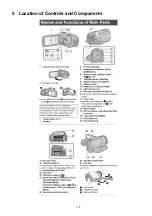
Page 15: ...15 5 Location of Controls and Components ...
Page 16: ...16 ...
Page 17: ...17 ...
Page 30: ...30 8 3 5 Removal of the Top OP Unit Fig D6 Fig D7 ...
Page 33: ...33 Fig D13 8 3 11 Removal of the Flash P C B Fig D14 ...
Page 37: ...37 8 3 18 Removal of the Barrier Case Unit Fig D25 Fig D26 ...
Page 39: ...39 Fig D30 Fig D31 Fig D32 ...
Page 40: ...40 8 3 21 Removal of the EVF Lens Holder Unit Fig D33 Fig D34 ...
Page 44: ...44 8 3 29 Removal of the MOS Unit Fig D44 8 3 30 Removal of the Stepping Motor Fig D45 ...


