Before attempting to connect or operate this product,
please read these instructions carefully and save this manual for future use.
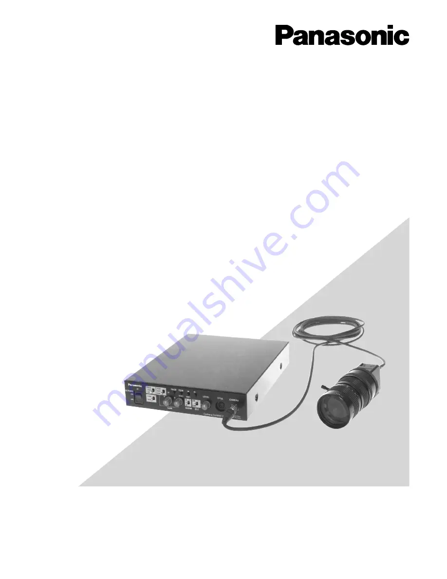
Operating Instructions
3 CCD Color Camera Head
Model No.
GP-US522HA
GP-US532HA
3 CCD Color Camera CCU
Model No.
GP-US522CUA
Lens : Purchased locally
Cable : Option


