©
2001 Matsushita Electric Works Ltd. All rights
reserved. Unauthorized copying and distribution is aviolation of law.
EY6535-U1
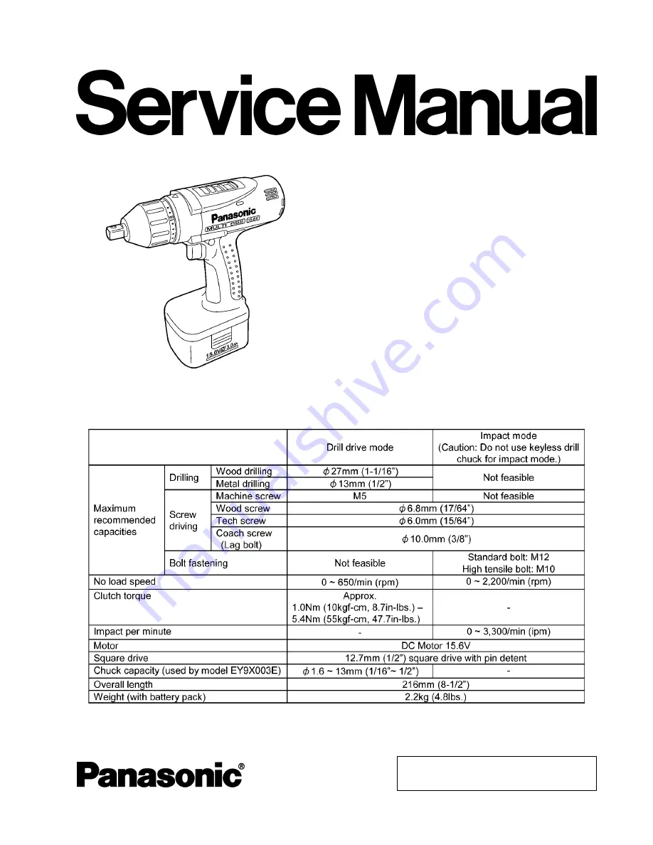
Cordless Multi Drill & Driver
SPECIFICATIONS
ORDER NO. PTD0108U32C1
F16
Page 1: ... 2001 Matsushita Electric Works Ltd All rights reserved Unauthorized copying and distribution is a violation of law EY6535 U1 Cordless Multi Drill Driver SPECIFICATIONS ORDER NO PTD0108U32C1 F16 ...
Page 2: ...G CONNECTION DIAGRAM 2 3 DISASSEMBLY INSTRUCTIONS 3 4 ASSEMBLY INSTRUCTIONS 6 5 TROUBLESHOOTING GUIDE 10 6 EXPLODED VIEW 12 7 REPLACEMENT PARTS LIST 13 CONTENTS Page Page 1 SCHEMATIC DIAGRAM 2 WIRING CONNECTION DIAGRAM 2 EY6535 U1 ...
Page 3: ...and take it out 2 Remove clutch handle slider and anvil 3 Remove 7 housing screws 4 Remove the click springs and separate housing A and B Ref No 1B Procedure 1A 1B Disassembly of Motor and Gear Box Block 1 Remove the motor assembly with the gear box block from the housing 2 Separate the motor assembly from the gear box block by twisting the motor to unlock tabs 3 EY6535 U1 ...
Page 4: ...rts can be remove one after another 3 Loosen 3 screws tightened with the motor mounting base Ref No 1D Procedure 1A 1B 1D Removal of Gear Box Assembly 1 Hold the driving carrier as illustrated Compress the assembly and remove the pin 2 Take out the driving shaft assembly and the gear case assembly from the shaft of the driving carrier NOTE Make sure not to lose the pin and the connect piece 4 EY65...
Page 5: ...pins 2 5 33 6 3 After removing pins the internal parts of the gear case assembly can be removed one after another thrust plate clutch gear planet gear 3pcs carrier thrust plate 4 Remove adjusting screw clutch spring and clutch plate 5 After removing the clutch plate 6 pieces of steel ball come off 5 EY6535 U1 ...
Page 6: ... Assemble clutch plate and clutch spring 4 Align the widest protrusion of adjusting screw with the narrower protrusion of gear case 5 Turn the adjusting screw into the gear case assembly one rotation for clockwise direction 6 Set the mode change handle on the wider protrusion of gear case 7 Confirm proper position of the mode change handle that both ends of spring must be put into the grooves of t...
Page 7: ...entified with blue adhesive 1 Tighten 3 screws of the motor mounting base 2 Assemble planet gears and pins with the revolving stand and insert them into the motor mounting base 3 The ring gear has its own correct direction Confirm the direction when the ring gear is inserted into the motor mounting base 4 Adjust the protrusion parts of ring gear with the groove parts of motor mounting base 7 EY653...
Page 8: ...pin into the shaft of the driving carrier holding the bottom of the gear box assembly driving carrier by hand 4 Align the wider protrusion of motor mounting base with the wider protrusion of gear case Ref No 2D Procedure 2A 2B 2C 2D Assembly of Motor and Switch 1 Fit terminal of lead wire black parallel to the heat sink Caution Be careful that the heat sink and the terminal do not touch otherwise ...
Page 9: ...Check that the widest protrusion 6mm of adjusting screw is in the middle and the mode change handle is set to the IMPACT position 3 Set anvil and slider has its own correct direction Confirm the direction when assembling 4 Set the clutch handle with position 1 on top 5 When setting fixation cover align mark on top 6 Tighten 4 screws 9 EY6535 U1 ...
Page 10: ...als for corrosion OK CHECK TERMINAL CONNECTIONS BETWEEN MAIN UNIT NO Clean and repair AND BATTERY PACK contacts Check for proper terminal contacts OK CHECK SWITCH BLOCK NO Contacts in switch block See WIRING CONNECTION DIAGRAM are defective Check continuity between following terminals Replace switch FET Inspection of the forward reverse selection switch block When switch handle is depressed all th...
Page 11: ... vary dependent upon the measurement range of the tester OK CHECK SWITCH BLOCK NO Replace switch FET block Weakness of CHECK ANVIL NO Replace anvil vibration Check wear condition If no less than 1mm from the corner at A side or 0 5mm from the corner at B side anvil is OK OK CHECK HAMMER BLOCK NO Replace driving shaft Check whether hammer block rotates smoothly when moving shaft of assembly hammer ...
Page 12: ...6 EXPLODED VIEW 12 EY6535 U1 ...
Page 13: ...Y6505L1347 PLANET GEAR B 3PCS PACK 3 19 WEY6535L1358 CLUTCH GEAR 1 20 WEY6535L0908 THRUST PLATE 1 21 WEY6535L0918 PIN 1 5 5 1 22 WEY6535L1368 DRIVING CARRIER 1 23 WEY6505L1457 RING GEAR 1 24 WEY6505L1377 PLANET GEAR A B 2PCS PACK 2 25 WEY6535L1388 REVOLVING STAND 1 26 WEY6505L0367 PIN C 5 9 4 2 27 WEY6505L9007 SCREW B K3 6 3PCS PACK 3 28 WEY6535L0028 MOTOR MOUNTING BASE 1 29 WEY6535L1008 DC MOTOR ...