background image

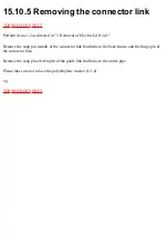
15.10.5 Removing the connector link

TOP


PREVIOUS


NEXT


Perform items 1-3 as directed in "3. Removal of Electric Lift Unit."

Remove the snap pin (small) of the connector link that links to the back frame, and the hinge pin of 

the connector link.

Remove the snap pins (left/right) of the guide link that links to the under-pipe.

Please take care not to lose the polyethylene washer (t=1.6).

•@

TOP


PREVIOUS


NEXT


Summary of Contents for EP790-C1

Page 1: ...mm Regional back rolling Automatic repetition within approx 120mm range Intensity adjustment Adjusts massage head protrusion steplessly within approx 45 mm range Shoulder position adjustment 7 steps Automatic shut off Approx 15 min Leg massager vibration Approx 3200 cycles min Shut off timer Approx 30 min Dimensions H x W x D Not reclined and leg rest retracted 1 050 x 755 x 1 050 mm Reclined and ...

Page 2: ... TOP NEXT ...

Page 3: ...s not possible Therefore upon arrival of the chair always follow thefollowing steps to initialize operating settings Check that the power switch is On found at the back of the hinge cover 1 Plug In 2 Push continuously the reclining button of the operation panel to raise the seatback 3 Continue the process until the seatback movement comes to a stop a clink sound should be audible The reclining mec...

Page 4: ... TOP PREVIOUS NEXT ...

Page 5: ...1 Installation TOP PREVIOUS NEXT 1 1 When Chair Arrives 1 2 Installation Position 1 3 Returning Chair to Packaged Configuration TOP PREVIOUS NEXT ...

Page 6: ...1 2 Installation Position TOP PREVIOUS NEXT To assure that the chair has enough space to recline to the rear please install it at least 40cm from the wall TOP PREVIOUS NEXT ...

Page 7: ...e returned to the packaged configuration please follow the following instructions 1 Insert the plug into the outlet and check that the power switch is On 2 While pushing down on the link release lever please push continuously the button of the operation panel After checking that the leg rest has not extended remove your hand fromthe link release lever When wanting to use the chair once again pleas...

Page 8: ... TOP PREVIOUS NEXT ...

Page 9: ...2 Hand control functions TOP PREVIOUS NEXT CONTROLLER Cover closed Programmed course massage Cover open Manual massage ...

Page 10: ... TOP PREVIOUS NEXT ...

Page 11: ...ement range of massage wheels TOP PREVIOUS NEXT 3 1 Upward massage Downward massage Rolling massage Regional rolling massage 3 2 Tapping Rolling Regional rolling Tapping rolling Regional tapping rolling TOP PREVIOUS NEXT ...

Page 12: ...ck to waist width 75mm minimum Intensity adjustment Upward and downward massage from gentle to strong 45mm wide adjustability where massage heads push out toward body as intensity increases Others from gentle to strong 15mm wide adjustability where massage heads push out toward body as intensityincreases TOP PREVIOUS NEXT ...

Page 13: ...stment Neck to waist Massage range width 3 5 16 in or 4 5 16 in 85mm or 110mm Intensity adjustment Tapping 45mm wide adjustability where massage heads push out toward body as intensity increases Others 15mm wide adjustability where massage heads push out toward body as intensity increases TOP PREVIOUS NEXT ...

Page 14: ...4 Components identification TOP PREVIOUS NEXT 4 1 PARTS IDENTIFICATION 4 2 TURNING ON THE POWER TOP PREVIOUS NEXT ...

Page 15: ...4 1 PARTS IDENTIFICATION TOP PREVIOUS NEXT TOP PREVIOUS NEXT ...

Page 16: ...4 2 TURNING ON THE POWER TOP PREVIOUS NEXT ...

Page 17: ...TOP PREVIOUS NEXT ...

Page 18: ...5 Required tools TOP PREVIOUS NEXT ...

Page 19: ...TOP PREVIOUS NEXT ...

Page 20: ...6 Simplified wiring diagram TOP PREVIOUS NEXT ...

Page 21: ... TOP PREVIOUS NEXT ...

Page 22: ...l system Inspection summary TOP PREVIOUS NEXT Prior to inspecting repairing the massage block please inspect the electrical system The section entitled No below refers to the Parts Number of the Expanded Drawings ...

Page 23: ...Prior to inspecting repairing the electromotion reclining please inspect the electrical system The section entitled No below refers to the Parts Number of the Expanded Drawings TOP PREVIOUS NEXT ...

Page 24: ...mode programmed operation buttons simultaneously turn on the power switch and continue to hold the buttons for approximately 5 seconds Release after the whole back LED lights up Next open the cover of the controller to reveal the manual operation side The manual operation side functions as a time display by pushing any of the manual operation buttons ...

Page 25: ...Display method Display it by utilizing LEDs of controller Unit 5 hours Time display of 5 5115 hours possible TOP PREVIOUS NEXT ...

Page 26: ......

Page 27: ...tation With the massage positiondetector P C B being 2 bits the massage position detector P C B is used to detect the timing of the increase decrease of the intensity The intensity adjustment block turns on when ON 5V Intensity adjustment P C B is composed of 3 bits It detects only intensity quantity and detects protruding quantity about 0 to 45 mm When dust and dirt get into the detector section ...

Page 28: ...art reset button is pushed to prevent overuse a timer begins After approximately 15 minutes time expires and the massage wheel goes into storage The leg massager is also on a timer to prevent overuse stops after 30 minutes TOP PREVIOUS NEXT ...

Page 29: ...age 1 Motor 2 Tapping belt 3 Tapping clutch 4 Massager belt 5 Massage clutch 6 Intermediate gear block 7 Drive pipe 8 Massage wheel block up down 1 Motor 2 Up down belt 3 Intensity adjustment block 4 Intensity adjustment belt 5 Up down clutch 6 Up down gear A 7 Up down shaft 8 Pinion A pinion B intensity adjustment ...

Page 30: ...1 Motor 2 Up down belt 3 Intensity adjustment block 4 Massage wheel block tapping 1 Motor 2 Tapping belt 3 Tapping clutch 4 Massage wheel block TOP PREVIOUS NEXT ...

Page 31: ...11 Motion of the clutch and belt based on various massager operations TOP PREVIOUS NEXT Massager operation and belt motion Massager operation and clutch motion ...

Page 32: ... TOP PREVIOUS NEXT ...

Page 33: ...OWN 2 Mount the massager on the lowest position of the back frame 3 Turn the hex nut M6 counterclockwise and move the massager upward 4 Make sure that the massager has been mounted horizontally by moving the massager to the position shown in the Figure Unless the massager has been mounted horizontally an abnormal sound or problem may occur 5 Move it up to the highest position until the massager st...

Page 34: ... button found on the manual operation panel of the controller 7 Install the rail piece A and B and tighten uniformly the set screws K3 6 left and right 3 pcs each 8 Using the manual operation of the controller conduct the rolling operation Set the massage heads adjustment switch to level 1 and check the up down stroke ...

Page 35: ... TOP PREVIOUS NEXT ...

Page 36: ...13 Removing the massage block TOP PREVIOUS NEXT 13 1 Removing the rear cover 13 2 Removing the massager TOP PREVIOUS NEXT ...

Page 37: ... Remove the fastener screw of the rear cover bottom middle Cup S K4 10 2 Pressing down the left and right side of lower part of rear cover the plastic cover is provided inside the ckoth pull it to this side to remove the rear cover TOP PREVIOUS NEXT ...

Page 38: ...the controller manual operation up down button to DOWN and then turn clockwise the up down clutch hex nut M6 see Figure 9 tomove to the position where the Pinion A and B block is visible from the back frame When the massager fails to move up and down turn clockwise the hex nut M6 of up down clutch The massager can be moved by attaching the hex socketø10 for nut 6 mm to a rechargeable drill driver ...

Page 39: ... ...

Page 40: ...TOP PREVIOUS NEXT ...

Page 41: ...ply Connecting cord for controller Power cord relay for leg massage TOP PREVIOUS NEXT 14 1 Cord arrangement of the connecting cord for power supply connecting cord for controller and power cord relay for leg massage TOP PREVIOUS NEXT ...

Page 42: ...he ground wires d and e 3 Arrange the wires in the cord guides so that they do not lift out then fix the cords using the metal fasteners 4 Install the massage block cover and attach the cord using the massage block cover clips 5 Wind the cord around the chair side cord wire one time 6 Attach the cord to the side surface of the frame f using an insulated tie 7 Band the cord together in the position...

Page 43: ... TOP PREVIOUS NEXT ...

Page 44: ...the tapping shaft assembly 15 4 Removing the tapping clutch 15 4 1 Assembling the tapping clutch 15 4 2 Assembling Procedure 15 4 3 Instructions when assembling 15 5 Removing the gear box 15 6 Removing and mounting the up down shaft bolt 15 6 1 Removing 15 6 2 Mounting 15 7 Assembling 15 7 1 Assembling the oval gear 15 8 Removing the right and left arms 15 9 Construction Electrical reclining leg r...

Page 45: ...cuits 15 10 3 Removal of electric lift unit 15 10 4 Points regarding assembly of the electrical lift unit 15 10 5 Removing the connector link 15 10 6 Points regarding connector link assembly 15 10 7 Points regarding fastening seat part lead wires cords TOP PREVIOUS NEXT ...

Page 46: ...t and intensity adjustment belt 3 Remove the intensity unit connector green and intensity sensor connector white 4 Remove the intensity sensor set screw A and remove the intensity sensor 5 Remove the K type stop ring 6 Remove the intensity unit set screws B and C 7 Remove the fitting part and withdraw If the intensity sensor has not been removed from the intensity adjustment unit the intensity adj...

Page 47: ...e bundle from the clip large and remove the motor lead wire connector white 2 Remove the massage belt tapping belt and intensity adjustment belt 3 Remove the motor ground wire set screw D 4 Remove the motor fitting set screw E to H and remove the motor TOP PREVIOUS NEXT ...

Page 48: ...he fitting part and remove the intensity adjustment unit 8 Remove the motor ground wire set screw D 9 Remove the motor fitting set screws E to H and remove the motor 10 Remove the shield panel fitted to the circuit set screw and idler pulley set screws I to M and remove the shield panel 11 Remove the motor side guide plate set screws N to U and remove the motor side guide plate When removing the s...

Page 49: ...ing clutch TOP PREVIOUS NEXT 1 Perform the removal steps 1 to 12 of 3 Removing the tapping shaft assembly 2 Remove the tapping clutch assembling screw Bind TP B3 20 remove the tapping gear box B and remove the tapping clutch ...

Page 50: ...15 4 1 Assembling the tapping clutch 15 4 2 Assembling Procedure 15 4 3 Instructions when assembling TOP PREVIOUS NEXT ...

Page 51: ...15 4 1 Assembling the tapping clutch TOP PREVIOUS NEXT After removing the tapping clutch from the tapping shaft assembly assemble them according to the specified procedure TOP PREVIOUS NEXT ...

Page 52: ...e shaft of tapping shaft assembly 2 Fit the E type stop ring to the shaft 3 Fit the tapping gear box A to the shaft 4 Check the direction of tapping clutch lead wire outlet and install the tapping clutch 5 Install the tapping gear box B 6 Fix with the tapping gear box assembling screw Bind TP B3 20 TOP PREVIOUS NEXT ...

Page 53: ...4 3 Instructions when assembling TOP PREVIOUS NEXT see Figure bottom If there is any clearance between the tapping gear boxes A and B it is impossible to insert into the hole of the motor side guide plate ...

Page 54: ...TOP PREVIOUS NEXT ...

Page 55: ... S to U 5 Remove the idler pulley set screws V and W and remove the idler pulley 6 Remove the eccentric link holding plate set screws X and Y with a spanner and remove the eccentric link holding plate 7 Remove the tapping shaft assembly as one unit without removing the guide plate for gear box and the guide plate for motor see Figure 8 Remove the gear box screws see Figure 9 After removing the scr...

Page 56: ......

Page 57: ... TOP PREVIOUS NEXT ...

Page 58: ...NEXT 1 To remove the up down shaft bolt the box driver Ø13 mm must be used To install the torque wrench withØ13 mm must be used 2 The torque wrench withØ13 mm socket and the box driver Ø13 mm are available as parts 15 6 1 Removing 15 6 2 Mounting TOP PREVIOUS NEXT ...

Page 59: ... of massager block left right are secured with the up down shaft bolts Remove them with the box driver Ø13 mm It is possible to use the Phillips head screwdriver But it may deform the screw head Therefore it is necessary to use the box driver TOP PREVIOUS NEXT ...

Page 60: ... 40 kgf cm If the up down shaft bolt has been insufficiently tightened it may loosen when the massager moves up and down and the massager may detach from the chair If the up down shaft bolt has been excessively tightened the bolt head may shear Tighten the up down shaft bolt of pinion A and pinion B while controlling the torque TOP PREVIOUS NEXT ...

Page 61: ...15 7 Assembling TOP PREVIOUS NEXT 15 7 1 Assembling the oval gear TOP PREVIOUS NEXT ...

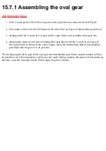
Page 62: ...e in the gear box 4 Alinging the mark of oval gear of intermediate gear block with the V mark of oval gear of drive pipe block as shown in the center Figure insert the intermediate shaft of intermediate gear block into the groove A of gear box When aligning the drive pipe block oval gear and intermediate gear block smooth rotation will not be possible even if the alignment is off by just one tooth...

Page 63: ... TOP PREVIOUS NEXT ...

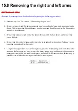
Page 64: ... its minimum 3 Remove the up down shaft bolt of the pinion B block with the box driver and remove the pinion B block 4 Remove the drive pipe bearing and remove the protrusion detecting plate Take care not to break the protrusion detecting plate 5 Using the massage wheel block removing tool grasp the thrust spring cover and remove the eccentric shaft stop spring Next remove the thrust spring cover ...

Page 65: ... TOP PREVIOUS NEXT ...

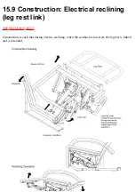
Page 66: ...15 9 Construction Electrical reclining leg rest link TOP PREVIOUS NEXT Construction is such that during electric reclining when the seatback is lowered the leg rest is linked and is extended ...

Page 67: ... TOP PREVIOUS NEXT ...

Page 68: ...al 15 10 2 Removing the under seat circuits 15 10 3 Removal of electric lift unit 15 10 4 Points regarding assembly of the electrical lift unit 15 10 5 Removing the connector link 15 10 6 Points regarding connector link assembly 15 10 7 Points regarding fastening seat part lead wires cords TOP PREVIOUS NEXT ...

Page 69: ...l of Electric Lift Unit Remove the snap pin small of the connector link that links to the back frame and the hinge pin of the connector link Remove the snap pins left right of the guide link that links to the under pipe Please take care not to lose the polyethylene washer t 1 6 TOP PREVIOUS NEXT ...

Page 70: ...15 10 6 Points regarding connector link assembly TOP PREVIOUS NEXT When installing install the polyethylene washers There is some amount of play in the drive part of the recliner ...

Page 71: ...TOP PREVIOUS NEXT ...

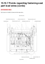
Page 72: ...15 10 7 Points regarding fastening seat part lead wires cords TOP PREVIOUS NEXT Each lead wire should be fastened with insulated ties ...

Page 73: ... TOP PREVIOUS NEXT ...

Page 74: ...16 Arranging massage block lead wires TOP PREVIOUS NEXT ...

Page 75: ...TOP PREVIOUS NEXT ...

Page 76: ...17 Actual wiring diagram TOP PREVIOUS NEXT ...

Page 77: ... TOP PREVIOUS NEXT ...

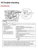
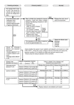
Page 78: ...18 Trouble shooting TOP PREVIOUS NEXT ...

Page 79: ......

Page 80: ......

Page 81: ......

Page 82: ... TOP PREVIOUS NEXT ...

Page 83: ...19 Other TOP PREVIOUS NEXT 19 1 Grease use 19 2 Examination after inspection and repairing 19 3 Q A 19 4 Instructions for trouble shooting in response to a customer s claim TOP PREVIOUS NEXT ...

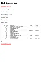
Page 84: ...19 1 Grease use TOP PREVIOUS NEXT Please grease during each repair Acceptable Grease Alvania RA light brown Molycoat white E paste yellow YM103 yellow TOP PREVIOUS NEXT ...

Page 85: ...k that the massage block operates using the controller Check that the massage block operates loaded i e sit in the chair and check Upon finishing repairs when placing the chair make sure that it has enough space to fully recline There should be more than 40cm between the wall and the chair when in the upright position TOP PREVIOUS NEXT ...

Page 86: ...19 3 Q A TOP PREVIOUS NEXT TOP PREVIOUS NEXT ...

Page 87: ...19 4 Instructions for trouble shooting in response to a customer s claim TOP PREVIOUS NEXT See regarding Grease use TOP PREVIOUS NEXT ...

Page 88: ...20 EXPLODED VIEW TOP PREVIOUS NEXT TOP PREVIOUS NEXT ...

Page 89: ...PLY LIFT 1 7 WEP1010L0598 COVER CLIP 1 8 WEP596L6627 SCREW CUP S K4 6 1 for mechanism 5 9 WEP755L6338 SCREW Cup 6ANGLE K4 10 1 for mechanism 20 10 WEP790L2100 MAIN CIRCUIT BOARD W COMPONENT 1 11 WEP755L9778 SCREW Cup S K3 8 1 for circuit board 4 12 WEP579L0031 SHIELD PANEL FOR P C B 1 13 WEP579L1001 MOTOR 1 14 WEP596L0237 GUIDE PLATE FOR MOTOR 1 15 WEP596L1117 TAPPING BELT 1 16 WEP596L6087 SCREW B...

Page 90: ...508 INTENSITY ADJUSTMENT BLOCK 1 37 WEP755L0467 INTENSITY ADJUSTMENT PLATE 1 38 WEP790L4958 INTENSITY ADJUSTMENT P C B 1 39 WEP569L0577 INTENSITY NUT CASE 1 40 WEP790L2389 CAPACITOR 1 41 WEP589L6997 SCREW TP BH4 60 1 for gear box 2 42 WEP589L6579 SCREW TP BH4 58 1 for gear box 2 43 WEP760L1797 GEAR BOX B 1 44 WEP579L4840 UP DOWN CLUTCH 1 45 WEP579L4830 MASSAGE CLUTCH 1 46 WEP570D4637 INTERMEDIATE ...

Page 91: ...AR 1 73 WEP579K9578 SCREW CUP S K4 16 1 for main frame 4 74 WEP759L0558 MAIN FRAME 1 75 WEP790L0529 MASSAGE MECHANISM COVER 1 76 WEP596K0457 SCREW 1 for cover 7 77 WEP790L0218 CORD GUIDE PLATE 1 78 WEP579L6638 SCREW SEMS K4 8 1 for mechanism 2 79 WEP790L2230 TRANSFORMER 1 80 WEP578L0288 BASE FOR TRANSFORMER 1 81 WEP578AL1307 PULLEY 1 82 WEP750L0167 SPRING WASHER GUIDE ROLLER 1 83 WEP760L0187 GROUN...

Page 92: ...INGE COVER 1 122 WEP755L0437 CABLE CLIP 1 123 WEP596K9597 SCREW TP S K5 16 1 for hinge cover 6 124 WEP760L0907 HINGE PIN 1 2 125 WEP596L0357 SNAP PIN 1 for hinge cover 7 126 WEP760L0877 HINGE PIN D 1 127 WEP596K0907 HINGE PIN 1 128 WEP790L1528 ELECTROMOTION RECLINING 1 129 WEP790K4460 CONTROLLER BLOCK 1 130 WEP790K3079 CONTROLLER HOUSING AB SET 1 131 WEP790L2160 CONTROLLER CIRCUIT BOARD W COMPONEN...

Page 93: ...IN 1 156 WEP760L0347 SNAP PIN SSP 6 1 157 WEP596L3747 CHASSIS C COVER 1 158 WEP790L2179 FOOT CIRCUIT BOARD W COMPONENT 1 159 WEP790L2259 TRANSFORMER B 1 160 WEP579L6638 SCREW SEMS M4 8 1 for transformer 3 161 WEP790K1548 DRIVE LINK 1 162 WEP790L0398 WASHER B 1 for drive link 2 163 WEP755K6488 SUPER LOCK NUT M6 1 for drive link 4 164 WEP596L5207 POLY SLIDER RING A 1 for drive link 4 165 WEP790K4989...

Page 94: ...179 WEP004W8507 INSULATED TIM SMALL A few 180 WEP004W8517 INSULATED TIE MEDIUM A few 181 WEP004W8527 INSULATED TIE LARGE A few 182 WEP000S8857 TORQUE WRENCH FOR UP DOWN SHAFT BOLT 1 183 WEP000S8867 BOX DRIVER FOR UP DOWN SHAFT BOLT 1 WEP790K8209 OUTER CARTON 1 WEP790L8118 INSTRUCTION BOOK LET 1 TOP PREVIOUS ...

Page 95: ......

Page 96: ......

Reviews: